Biosensor with rf signal transmission

Inactive Publication Date: 2006-01-26
KONINKLIJKE PHILIPS ELECTRONICS NV
View PDF16 Cites 29 Cited by
  • Summary
  • Abstract
  • Description
  • Claims
  • Application Information

AI Technical Summary

Benefits of technology

[0029] In respect of both types of known devices the sensitivity is greatly increased (by eliminating possible unreliabilities), while the complexity of th

Problems solved by technology

It is however a disadvantage of the known biosensor cartridge, that the sensitivity and correctness of the output is dependent on the strength of the fluorescent signal.
Thus, if an intermediate medium distorts the signal from the biosensor, the resulting measureme

Method used


Image

  • Biosensor with rf signal transmission
  • Biosensor with rf signal transmission
  • Biosensor with rf signal transmission

Examples


Embodiment Construction

[0047] The present invention will be described with respect to a number of embodiments and with reference to certain drawings but the invention is not limited thereto.

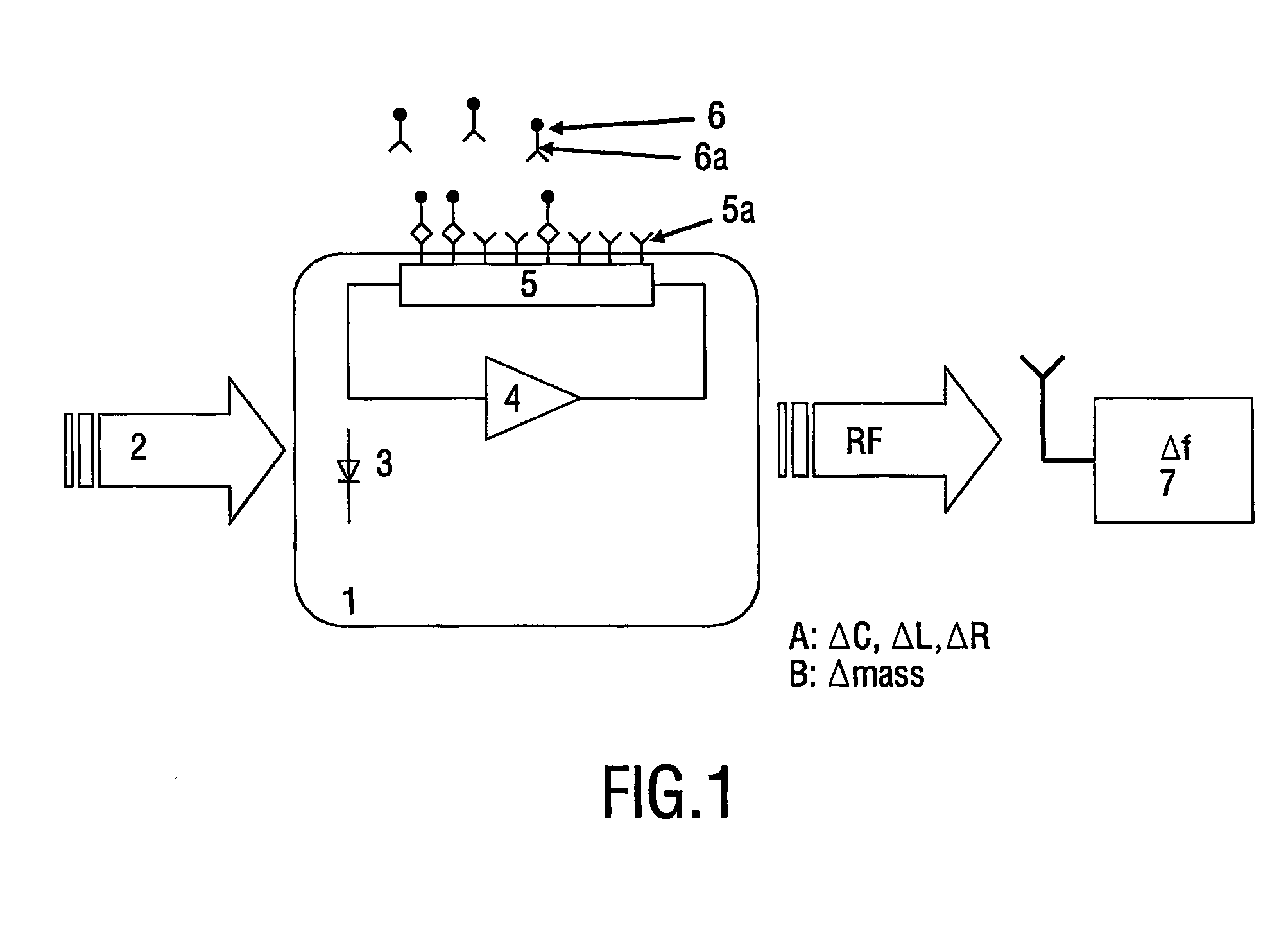
[0048]FIG. 1 is a schematic representation of the device and method in accordance with the invention. A biosensor cartridge 1 is provided with a photodiode 3 as a remote power transmission element. By shining light 2 on the photodiode the device is provided with power. The light may be visible light, UV or IR light, in an example the wavelength of the light is 780 nm. The device further comprises an oscillator circuit comprising in this example at least an amplifier 4 and a sensor element 5. The resonance frequency (eigenfrequency) is dependent on the properties of the elements forming the resonance circuit, in particular e.g. the capacitance, the inductance or the resistance of the sensor element within the oscillator circuit. Also the mass could have an influence on the oscillating frequency. The device 1 comprises ...


PUM

PropertyMeasurementUnit
Poweraaaaaaaaaa
Frequencyaaaaaaaaaa

Abstract

A device (1) and method for measuring and or detecting the presence of biomolecules. The device comprises a resonance circuit arranged to operate and emit a resonance frequency (f). The resonance circuit comprises or is coupled to a sensor element (5) for detecting the binding of biomolecules (6a) to binding sites (5a). The binding of the biomolecules changes a physical property (R, L, C. mass) of the sensor element (5), which in it's turn, either directly when the sensor element forms part of the resonance circuit, or via a coupling of the sensor element to the resonance circuit, the resonance frequency. The change in the resonance frequency is detected. The device comprises a remote power transmission element, such as a photodiode or coil, for providing power to the resonance circuit using light or RF radiation respectively.

Description

BACKGROUND OF THE INVENTION [0001] This invention relates to a device comprising a sensor element having biomolecular binding sites for a biomolecule and a method for detecting biomolecules in samples using such a device. Such devices are sometimes also called biosensors cartridges, the sensor elements are sometimes called biosensors. Biochips, biosensor chips, biological microchips, gene-chips or DNA chips are other words used to described such devices or sensors. In such a device a signal is caused by an interaction of the binding sites on a sensor surface with biochemical components in a fluid. Typically a fluid component binds specifically to molecules forming the bonding sites on a surface of the sensor element. The invention also relates to a method for determining the presence of or for measuring the amount of biomolecules using a biosensor device. [0002] Biosensors have been used to determine the presence and / or the concentration of biomolecules in fluids. Examples of biomol...

Claims


Application Information

Patent Timeline
IPC IPC(8): C12M1/34C12Q1/68G01N27/00G01N27/02G01N29/02G01N29/036G01N33/543
CPCG01N27/745G01N29/022G01N29/036G01N2446/00G01N2291/0256G01N2291/0423G01N2291/0426G01N33/48792
Inventor KAHLMAN, JOSEPHUS ARNOLDUS HENRICUS MARIAPRINS, MENNO WILLEM JOSEVAN HOUTEN, HENDRIK
Owner KONINKLIJKE PHILIPS ELECTRONICS NV
Why Eureka
Try Eureka