
Frequency and/or phase compensated microelectromechanical oscillator

a micro-electromechanical and oscillator technology, applied in the field of frequency and/or phase compensation of micro-electromechanical oscillators, can solve the problems of increasing the cost and difficulty of manufacture of the resonant structure, difficult stability and control of the oscillator, and requiring costly control circuits

Active Publication Date: 2006-02-02
ROBERT BOSCH GMBH
View PDF99 Cites 14 Cited by
  • Summary
  • Abstract
  • Description
  • Claims
  • Application Information

AI Technical Summary

Benefits of technology

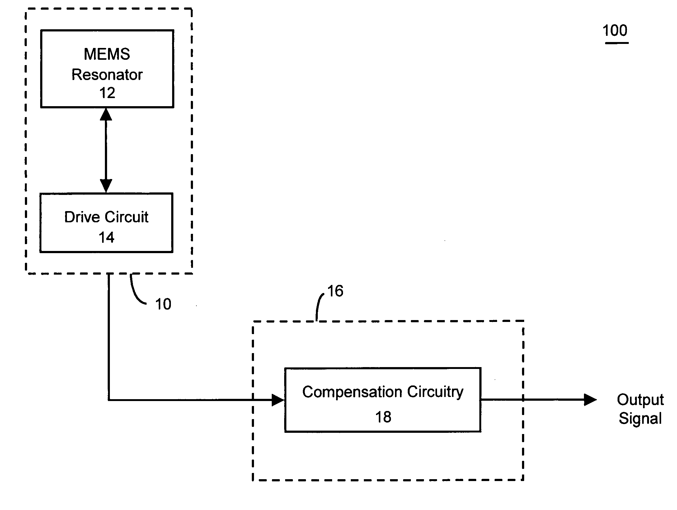
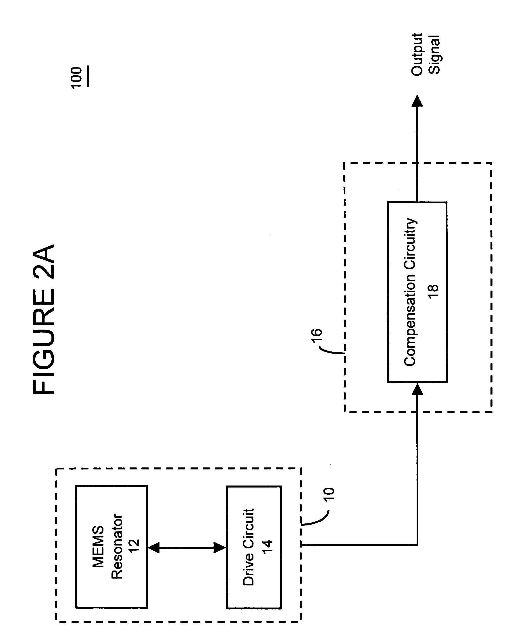
The present invention is about a compensated microelectromechanical oscillator that can adjust its output frequency based on the temperature of the microelectromechanical resonator. The frequency adjustment circuitry can include frequency multiplier circuitry and frequency divider circuitry, which can dynamically determine the output frequency based on the frequency of the output signal of the microelectromechanical resonator and the temperature of the resonator. The method of programming the microelectromechanical oscillator involves measuring the first frequency of the output signal and calculating a set of values to adjust the frequency. The technical effect of this invention is to provide a compensated microelectromechanical oscillator that can automatically adjust its output frequency based on the temperature of the resonator, without the need for manual adjustment.

Problems solved by technology

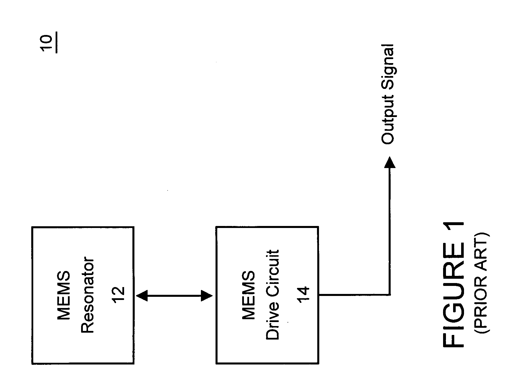
However, such a resonator tends to make frequency adjustment, stability and control of the oscillator difficult, complicated and expensive.
In order to achieve high frequencies of the output signal, the necessary gap and voltages tend to complicate the MEMS design, significantly increase the cost and difficulty of manufacture of the resonant structure, and / or require costly control circuitry (for example, high-voltage CMOS circuitry).
While this technique may offer precision and / or control, the design of the MEMS resonant structure is considerably more complicated.
In addition, such a MEMS design often requires additional power as well as temperature adjustment circuitry to control the temperature of the resonant structure.
As such, this alternative may not be suitable for many applications.

Method used


Image

  • Frequency and/or phase compensated microelectromechanical oscillator
  • Frequency and/or phase compensated microelectromechanical oscillator
  • Frequency and/or phase compensated microelectromechanical oscillator

Examples


Embodiment Construction

[0048] There are many inventions described and illustrated herein. In one aspect, the present invention is directed to a frequency and / or phase compensated MEMS oscillator (hereinafter “frequency / phase compensated MEMS oscillator” or “compensated MEMS oscillator”) for providing a highly accurate, stable, controllable, programmable, definable and / or selectable output signal(s). In this regard, the controllable, programmable, definable and / or selectable aspect of the output signal(s) may be the frequency and / or phase of the output signal. For example, the present invention may provide a highly accurate, stable, controllable, programmable, definable and / or selectable output signal(s) having a predetermined, predefined and / or specific frequency (for example, a lower frequency of 1 Hz to 100 kHz, a more moderate frequency of 1-100 MHz or a higher frequency of 1-10 GHz) and / or a desired phase (for example, 0°, 90° and / or 180°). Indeed, the frequency and / or phase of the output signal may b...


PUM


Abstract

There are many inventions described and illustrated herein. In one aspect, the present invention is directed to a compensated microelectromechanical oscillator, having a microelectromechanical resonator that generates an output signal and frequency adjustment circuitry, coupled to the microelectromechanical resonator to receive the output signal of the microelectromechanical resonator and, in response to a set of values, to generate an output signal having second frequency. In one embodiment, the values may be determined using the frequency of the output signal of the microelectromechanical resonator, which depends on the operating temperature of the microelectromechanical resonator and / or manufacturing variations of the microelectromechanical resonator. In one embodiment, the frequency adjustment circuitry may include frequency multiplier circuitry, for example, PLLs, DLLs, digital / frequency synthesizers and / or FLLs, as well as any combinations and permutations thereof. The frequency adjustment circuitry, in addition or in lieu thereof, may include frequency divider circuitry, for example, DLLs, digital / frequency synthesizers (for example, DDS) and / or FLLs, as well as any combinations and permutations thereof.

Description

[0001] This invention relates to microelectromechanical systems and techniques including microelectromechanical resonators; and more particularly, in one aspect, to a system and technique for providing a stable and controllable microelectromechanical oscillator output frequency that is controllable in fine and coarse increments. [0002] Microelectromechanical systems (“MEMS”), for example, gyroscopes, resonators and accelerometers, utilize micromachining techniques (i.e., lithographic and other precision fabrication techniques) to reduce mechanical components to a scale that is generally comparable to microelectronics. [0003] MEMS typically include a mechanical structure fabricated from or with, for example, a silicon layer using micromachining techniques. The silicon layer is disposed on, for example, an insulation layer that, among other things, serves as a sacrificial layer for the MEMS. As such, significant portions of the insulation layer are etched or removed in order to releas...

Claims


Application Information

Patent Timeline
Patent Type & Authority Applications(United States)
IPC IPC(8): H03J7/04H03B5/04H03B5/30H03L1/02H03L1/04H03L7/07H03L7/081H03L7/197
CPCH03B5/04H03B5/30H03L1/022H03L1/026H03L7/1974H03L1/04H03L7/07H03L7/08H03L7/0812H03L1/027H03L7/081H03L7/197
Inventor PARTRIDGE, AARONLUTZ, MARKUS
Owner ROBERT BOSCH GMBH
Learn More