
Host control for a variety of tools in semiconductor fabs

Inactive Publication Date: 2006-02-02
GLOBALFOUNDRIES INC
View PDF4 Cites 9 Cited by
  • Summary
  • Abstract
  • Description
  • Claims
  • Application Information

AI Technical Summary

Benefits of technology

[0017] Another feature of the invention is that a process of tool control is divided into units of work

Problems solved by technology

No known HCS can connect to different 300 mm tool types without requiring code changes in the original software.
Further, current HCS programs do not allow runtime behavior modification without disrupting communications between the tool and the manufacturing execution system or the processing of the product.
In addition, current HCS does not provide a mechanism to perform performance diagnostics on semi compliant equipment and equipment control systems to run diagnostic tests to improve the performance of the ecs and other systems.

Method used


Image

  • Host control for a variety of tools in semiconductor fabs
  • Host control for a variety of tools in semiconductor fabs
  • Host control for a variety of tools in semiconductor fabs

Examples


Embodiment Construction

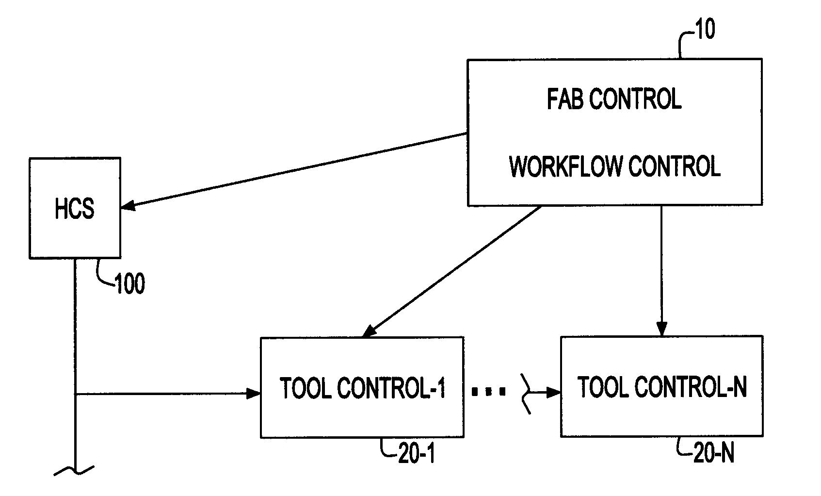
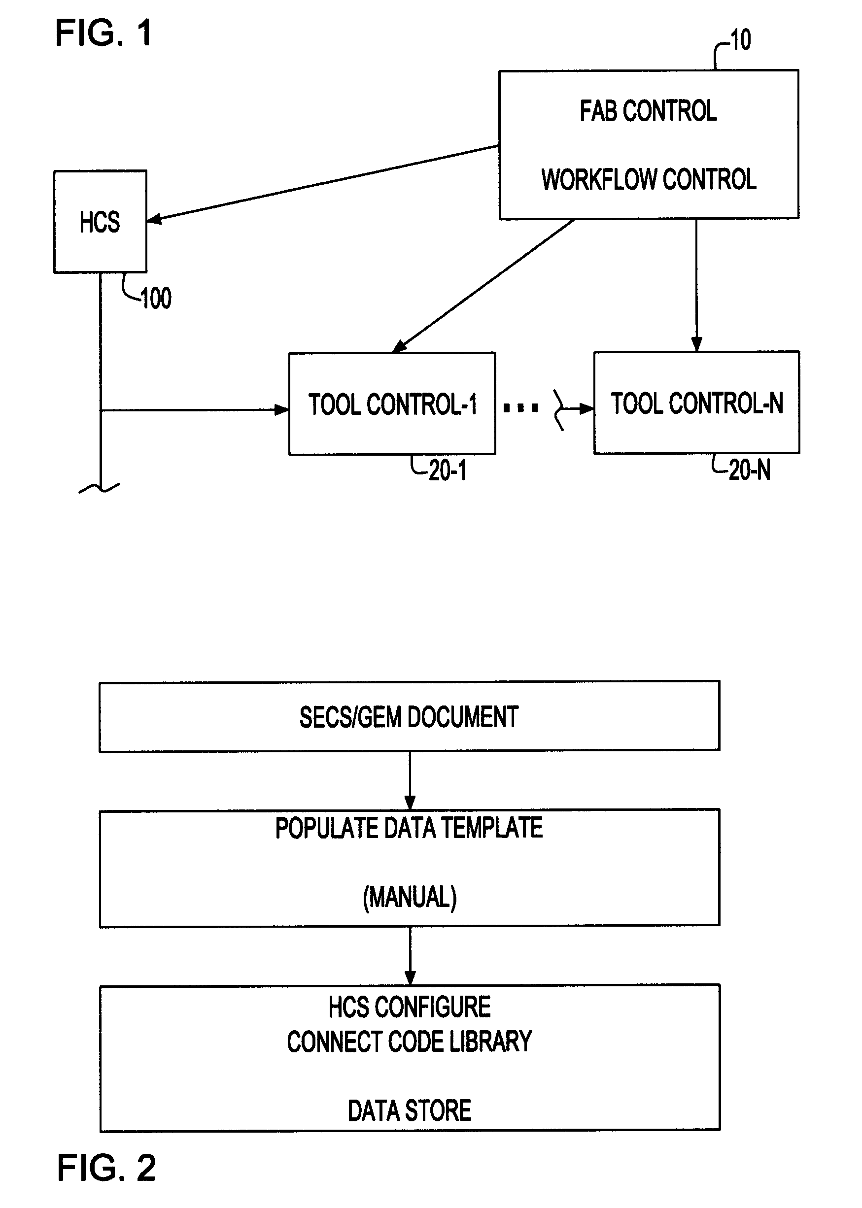
[0023]FIG. 1 illustrates an example of a fab control system employing the invention, in which block 10 represents an overall system, referred to as a manufacturing execution system or MES, that is aware of the status of all wafers in the fab and directs them to the sequential steps in the process.

[0024] On the lower right of the Figure, boxes 20-1-20-n represent individual tools. Box 100, on the lower left, represents a program according to the invention, referred to as a host control system or HCS, that receives commands from the master system and passes commands on to the individual (one or more) tools. The commands may simply be passed through, or they may be a relatively high level command that results in a number of lower level commands to the tool. In addition, the HCS will monitor the tool or tools and adjust communication in order to improve fab performance.

[0025] In the past, differences in tool types required that the control software (either the global control on an int...


PUM


Abstract

A software module for use within an integrated circuit fabrication facility sends commands to a tool according to a method that operates with any tool that satisfies SEMI standards to add or subtract steps in a process without reprogramming or recompiling. The program operates autonomously to change parameters of commands that it sends to the tool to improve performance of the fab.

Description

BACKGROUND OF INVENTION [0001] 1. Technical Field [0002] The field of the invention is that of integrated circuit fabrication, in particular controlling the operation of a variety of processing tools in a fabrication facility (fab). [0003] 2. Background of the Invention [0004] In modern integrated circuit processing technology, there are several kinds of equipment in a fab, typically produced by different manufacturers. [0005] The basic processes of forming an integrated circuit include depositing a layer of material on a substrate, defining a pattern in a layer of photoresist and etching the pattern that was defined to transfer the pattern to the layer. Those skilled in the art are aware of positive and negative patterns, implantation, and other processes. [0006] The machines that perform the individual processing steps are computer controlled and perform their function in response to stored parameters. For example, a chemical vapor deposition tool will have stored values for the f...

Claims


Application Information

Patent Timeline
IPC IPC(8): G06F19/00
CPCG05B2219/45031G05B19/41865Y02P90/02
Inventor CHUKKA, PADMAVATHI D.DU, YINGHERBOLD, BARRY M. IIHERTA, BENJAMIN W.KUNKA, KRITHIKPRIYA R.LIANG, FRANK T.MACHUGH, ROBERT J.MURGAI, SORABHO'LEARY, THOMAS T.OZA, CHINMAY S.PARIMI, RAKESH K.SOYKA, MARTIN J.
Owner GLOBALFOUNDRIES INC
Learn More