Metal interconnect features with a doping gradient

Inactive Publication Date: 2006-02-09
TAIWAN SEMICON MFG CO LTD
View PDF8 Cites 11 Cited by
  • Summary
  • Abstract
  • Description
  • Claims
  • Application Information

AI Technical Summary

Benefits of technology

[0010] To achieve the foregoing and other objects, and in accordance with the purposes of the present invention, as embodied and broadly described h

Problems solved by technology

Consequently, the aspect ratios for the features, i.e., their height divided by width, has increased thereby creating additional challenges in adequately filling the sub-micron features with, for example, copper metal.
Several problems are created by prior

Method used


Image

  • Metal interconnect features with a doping gradient
  • Metal interconnect features with a doping gradient
  • Metal interconnect features with a doping gradient

Examples


Embodiment Construction

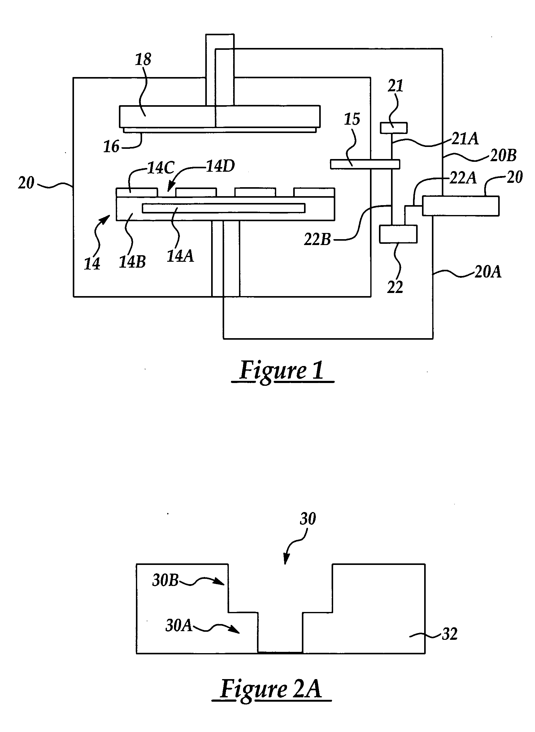
[0017] In the method and exemplary copper interconnect feature formed according to the present invention, the invention is explained by reference to an exemplary electrode assembly. It will be appreciated that the method and copper interconnect structure of the present invention may be formed by any copper plating system including an anode, and a cathode and at least one reference electrode, preferably having the ability to carry out pulsed waveform plating according to preferred embodiments.

[0018] For example, referring to FIG. 1 is shown a schematic view of an exemplary copper electrochemical deposition (ECD) system for carrying out an ECD process according to embodiments of the present invention. A consumable copper or copper alloy anode 14, for example having a diameter about the same or larger than a process wafer is disposed in spaced apart relationship facing the cathode (process wafer) 16. The process wafer 16 is supported on a rotatable support e.g., 18, for example held i...


PUM

PropertyMeasurementUnit
Percent by atomaaaaaaaaaa

Abstract

A metal filled damascene structure with improved electromigration resistance and method for forming the same, the method including providing a semiconductor process wafer comprising damascene openings; and, depositing metal and at least one metal dopant according to an ECD process to from a metal filled damascene comprising a doped metal alloy portion.

Description

FIELD OF THE INVENTION [0001] This invention generally relates to metallic electrodeposition methods and more particularly to a gradiently doped metal interconnects and method of forming the same to improve the structural stability and resistance to electromigration of metal interconnects incorporated into integrated circuits. BACKGROUND OF THE INVENTION [0002] Sub-micron multi-level metallization is one of the key technologies for the next generation of ultra large-scale integration (ULSI). The multilevel interconnects that lie at the heart of this technology including for example, vias and metal interconnect lines, are required to withstand both thermal and electrical stresses over an extended period of time in order to form reliable integrated circuits. Formation of these interconnect features is very important to the success of ULSI and to the continued effort to increase circuit density and quality of integrated circuits. [0003] Copper and copper alloys have become the metal of...

Claims


Application Information

Patent Timeline
IPC IPC(8): C25D5/18C25D7/12
CPCC25D5/18C25D7/123H01L21/76877H01L21/2885
Inventor CHANG, CHUNG LIANGTSAI, MING HSINGSHUE, WINSTON S.
Owner TAIWAN SEMICON MFG CO LTD
Why Eureka
Try Eureka