
Semiconductor devices having a support structure for an active layer pattern and methods of forming the same

a technology of active layer pattern and support structure, which is applied in the direction of semiconductor devices, instruments, photomechanical treatment, etc., can solve the problems of ion implantation, ineffective isolation method, and difficulty in preventing adjacent semiconductor devices from interfering with one another

Active Publication Date: 2006-02-09
SAMSUNG ELECTRONICS CO LTD
View PDF9 Cites 42 Cited by
  • Summary
  • Abstract
  • Description
  • Claims
  • Application Information

AI Technical Summary

Benefits of technology

[0016] In some embodiments of the present invention, the gate electrode pattern defined support structure prevents the gate insulation layer and the active layer pattern from collapsing after forming a void under the active region. The sacrificial layer pattern may be removed through wet etching and / or dry etching. The sacrificial layer pattern may be removed through isotropic dry etching using an etchant including peracetic acid and a mixture of H2O2, HF, and / or CH3COOH. The gap-filling insulation layer may be an oxide layer, a nitride layer, and / or a silicon layer. The gap-filling insulation layer may be a stack structure including a first oxide layer, a nitride layer, and a second oxide layer.
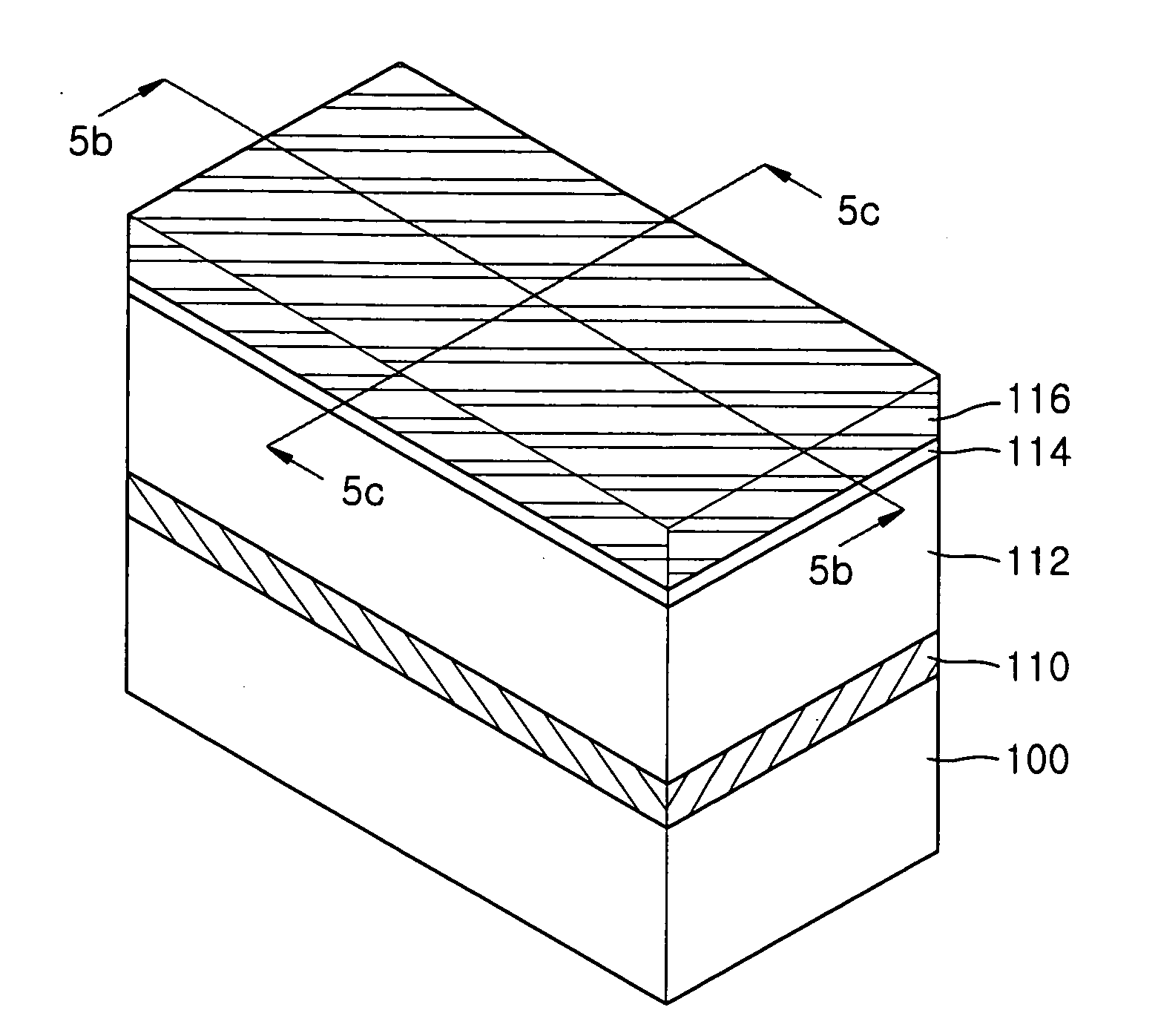
[0018] In further embodiments of the present invention, forming an active region includes forming a fin-shaped active region protruding from the semiconductor substrate. The methods further include forming a gate insulation layer on a top surface of the active layer pattern and forming a first hard mask pattern on the gate insulation layer. In such embodiments, forming a support structure includes forming a gate electrode pattern that extends along the top surface of the first hard mask pattern and the sidewalls of the active layer pattern and the sacrificial layer pattern. The first hard mask pattern may be a silicon nitride layer. The sidewalls of the first hard mask pattern may be aligned with sidewalls of the active layer pattern and the sacrificial layer pattern. The gate electrode pattern defined support structure may prevent the gate insulation layer and the active layer pattern from collapsing after forming a void under the active region. After the filling the formed void with the gap-filling insulation layer, the gap-filling insulation layer and the active layer pattern may be removed such that a predetermined region of the semiconductor wafer is exposed.

Problems solved by technology

As a result, it has become more difficult to prevent adjacent semiconductor devices from interfering with one another using conventional isolation methods, such as local oxidation of silicon (LOCOS) or trench isolation.
This type of ion implantation, however, may not be an efficient approach to provide isolation where the distance between semiconductor devices is decreased beyond the point where this type of ion implantation is effective due to the increase of the integration density of the semiconductor devices.
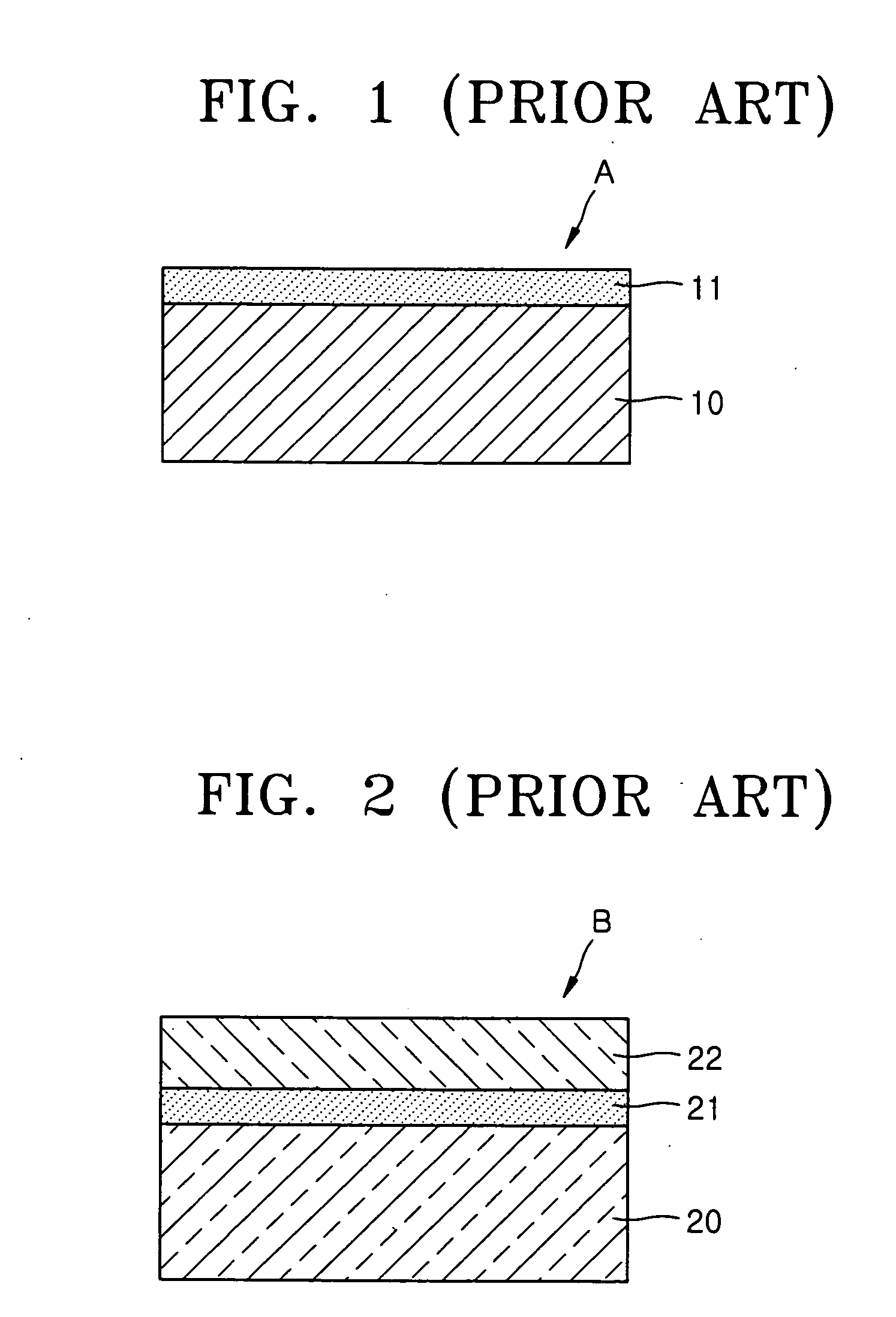
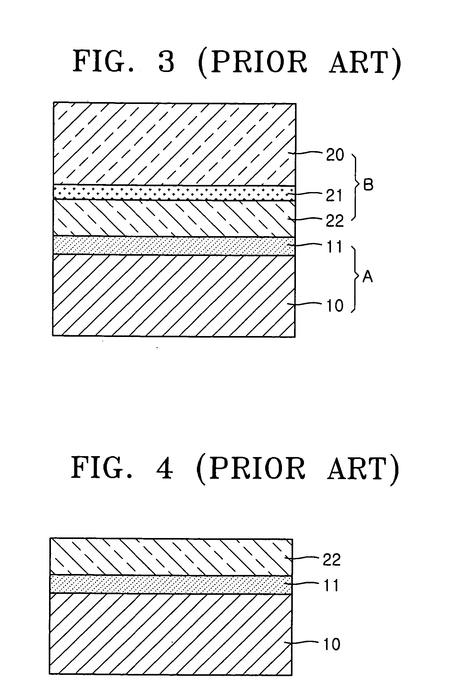
In other words, an SOI structure region typically should be formed in a semiconductor wafer by using the processes illustrated in FIGS. 1 through 4, and then a bulk silicon region should be formed by removing the SOI structure region from the semiconductor wafer, which typically results in an increase in the manufacturing costs of the semiconductor devices and may make mass production of the semiconductor devices more difficult and / or expensive.

Method used


Image

  • Semiconductor devices having a support structure for an active layer pattern and methods of forming the same
  • Semiconductor devices having a support structure for an active layer pattern and methods of forming the same
  • Semiconductor devices having a support structure for an active layer pattern and methods of forming the same

Examples


Embodiment Construction

[0027] The invention is described more fully hereinafter with reference to the accompanying drawings, in which embodiments of the invention are shown. This invention may, however, be embodied in many different forms and should not be construed as limited to the embodiments set forth herein. Rather, these embodiments are provided so that this disclosure will be thorough and complete, and will fully convey the scope of the invention to those skilled in the art. In the drawings, the size and relative sizes of layers and regions may be exaggerated for clarity.

[0028] It will be understood that when an element or layer is referred to as being “on”, “connected to” or “coupled to” another element or layer, it can be directly on, connected or coupled to the other element or layer or intervening elements or layers may be present. In contrast, when an element is referred to as being “directly on,”“directly connected to” or “directly coupled to” another element or layer, there are no interveni...


PUM


Abstract

Semiconductor devices include a semiconductor substrate with a stack structure protruding from the semiconductor substrate and surrounded by an isolation structure. The stack structure includes an active layer pattern and a gap-filling insulation layer between the semiconductor substrate and the active layer pattern. A gate electrode extends from the isolation structure around the stack structure. The gate electrode is configured to provide a support structure for the active layer pattern. The gate electrode may be a gate electrode of a silicon on insulator (SOI) device formed on the semiconductor wafer and the semiconductor device may further include a bulk silicon device formed on the semiconductor substrate in a region of the semiconductor substrate not including the gap-filing insulation layer.

Description

CROSS-REFERENCE TO RELATED APPLICATION [0001] This application is related to and claims priority from Korean Patent Application No. 2004-61954 filed on Aug. 6, 2004, the disclosure of which is hereby incorporated herein by reference in its entirety. BACKGROUND OF THE INVENTION [0002] The present invention relates to semiconductor devices, and more particularly, to semiconductor devices having a channel region and a method of manufacturing the same. [0003] As the integration density of semiconductor (integrated circuit) devices increases, the distance between respective devices fabricated on a substrate of a semiconductor device decreases. As a result, it has become more difficult to prevent adjacent semiconductor devices from interfering with one another using conventional isolation methods, such as local oxidation of silicon (LOCOS) or trench isolation. Ion implantation to limit or prevent punch-through at a lower portion of an isolation layer has been proposed to address a latch-u...

Claims


Application Information

Patent Timeline
IPC IPC(8): G03F7/00
CPCH01L21/84H01L27/12H01L21/76224H01L29/785H01L29/66833H01L29/66795H01L21/18
Inventor OH, CHANG-WOOPARK, DONG-GUNKIM, DONG-WONLI, MINGKIM, SUNG-HWAN
Owner SAMSUNG ELECTRONICS CO LTD
Learn More