
Method and apparatus of mechanical stage positioning in virtual microscopy image capture

Active Publication Date: 2006-02-16
OLYMPUS AMERICA
View PDF71 Cites 58 Cited by
  • Summary
  • Abstract
  • Description
  • Claims
  • Application Information

AI Technical Summary

Benefits of technology

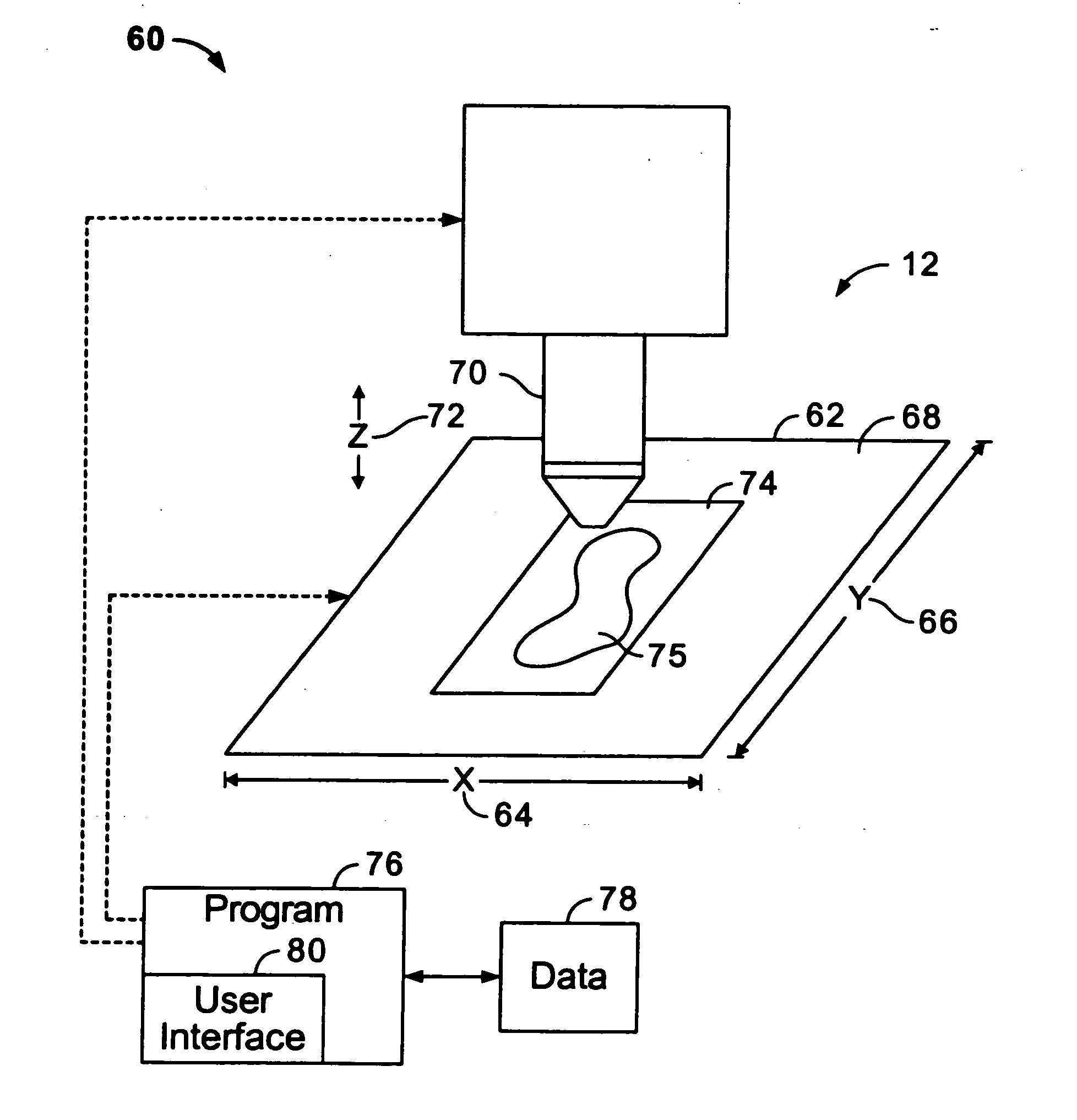
[0008] In accordance with the present invention, there is disclosed a new and less expensive method and apparatus, as contrasted to the prior art, for constructing a virtual microscope slide comprised of digitally scanned images from a microscope sample such as a tissue specimen or the like. This is achieved by replacing the conventional highly precise x and y stage platform with a significantly less accurate and less precise x and y stage platform and using a larger image sensor to provide feedback control to compensate for positioning inaccuracies. The larger image sensor enables a much larger image capture. By retaining only the center portion of the image as the virtual slide data structure tile, the larger area of image capture surrounding the center portion can be used to align images to compensate for stage inaccuracies and to provide a feedback control signal to replace the conventional optically encoded feedback control signal. The purpose of the feedback control is to maintain the capture image in the center of the larger imaged sensor so that overlapping areas for image alignment are always present.

Problems solved by technology

In a digital imaging microscope the field of view is the area of the illuminated field diaphragm of the microscope optical system as viewed in the specimen plane using a magnifying objective and is further limited by the sensing area of the image capture device.
Both methods are limited with regard to the size of image that can be captured at one time by the size of the optical field of view without moving the stage to perform the subsequent image captures.
These systems are expensive, with one of the major components being the highly precise stages necessary to preserve image alignment.
Unfortunately, such highly precise stages are very expensive.
However, this introduces a positional error related to the step size of the stage being larger than the size of the pixel element in the image plane.
The stage can only move in incremental amounts which usually does not evenly match the image width in pixels, producing an error of several pixels between images.
This introduces additional errors of non-linearity.
This error, and mechanical hysteresis, is usually corrected by expensive optical encoder feed back control.
This can cause alignment errors of as much as 40 pixels between images without feedback control.

Method used


Image

  • Method and apparatus of mechanical stage positioning in virtual microscopy image capture
  • Method and apparatus of mechanical stage positioning in virtual microscopy image capture
  • Method and apparatus of mechanical stage positioning in virtual microscopy image capture

Examples


Embodiment Construction

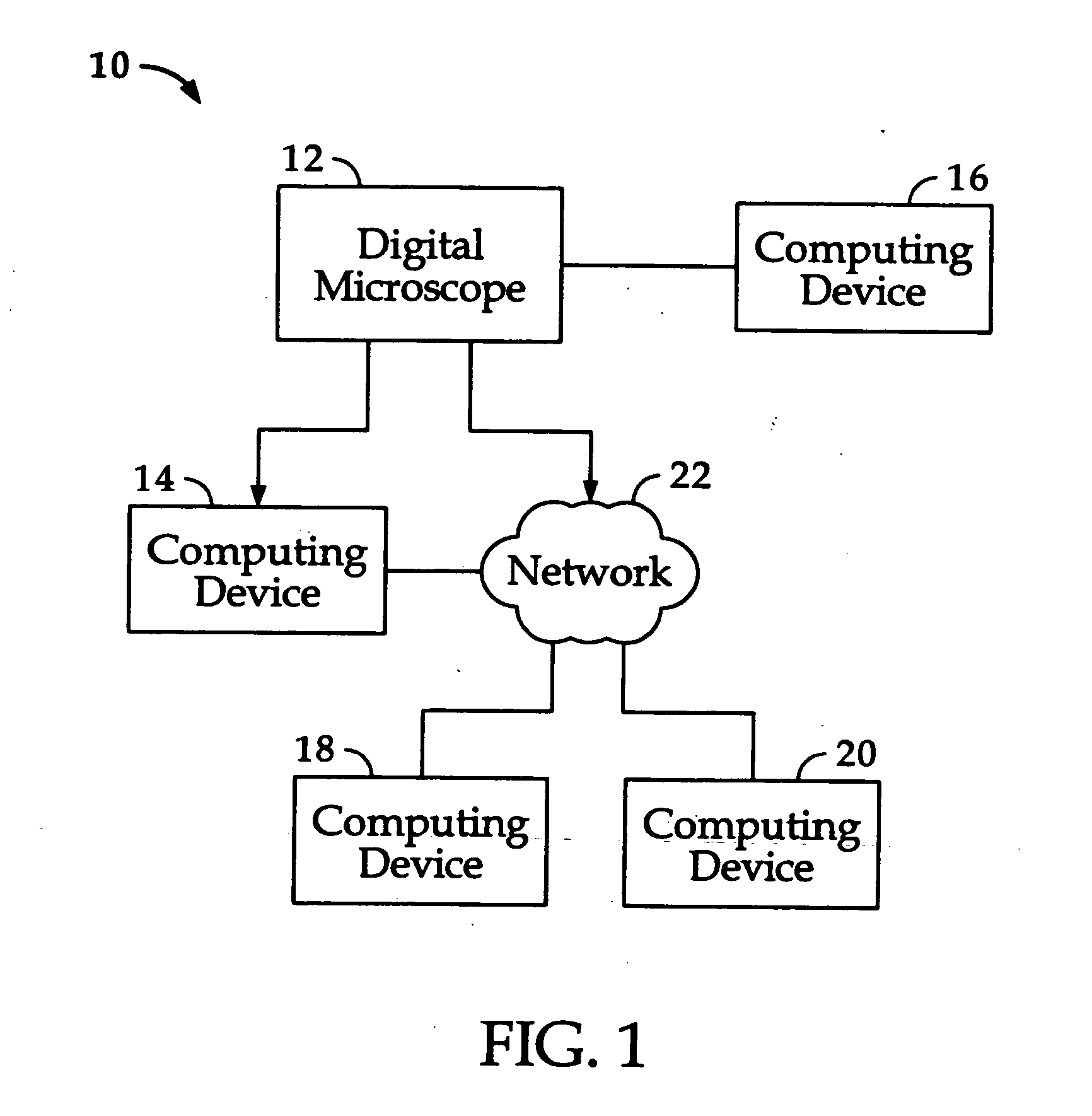
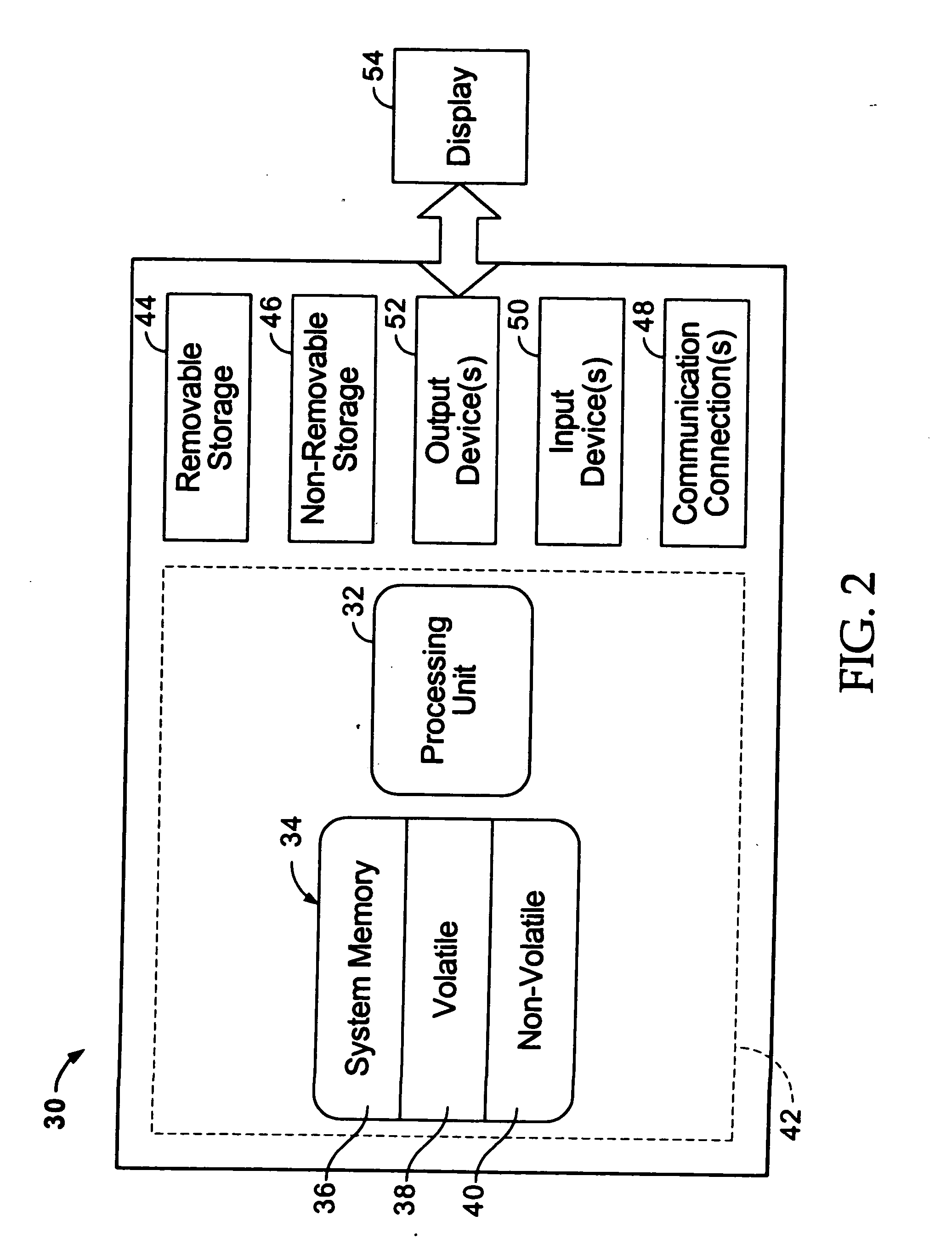
[0018] Prior to proceeding with a description of the various embodiments of the invention, a description of the computer and networking environment in which the various embodiments of the invention may be practiced will now be provided. Although it is not required, the present invention may be implemented by programs that are executed by a computer. Generally, programs include routines, objects, components, data structures and the like that perform particular tasks or implement particular abstract data types. The term “program” as used herein may connote a single program module or multiple program modules acting in concert. The term “computer” as used herein includes any device that electronically executes one or more programs, such as personal computers (PCs), hand-held devices, multi-processor systems, microprocessor-based programmable consumer electronics, network PCs, minicomputers, mainframe computers, consumer appliances having a microprocessor or microcontroller, routers, gat...


PUM


Abstract

A method and apparatus for creating a magnified composite image of a microscope specimen comprises making error corrections for imprecise movements of the specimen relative to an objective lens when capturing data for first and second images. A correction offset is computed based on a comparison of data for overlapped portions of the first and second images and then the specimen is moved through a distance modified by the correction offset for capture of a subsequent tiled image. Image center portions are retained as the data structure tile. The area about the center portion is used to align images and to compensate for stage inaccuracies and to provide a feedback signal for a drive system. Differences in X,Y coordinates for macro and micro view images may be used as navigation offsets to view a selected point for the micro image marked on the macro image.

Description

CROSS-REFERENCE TO RELATED APPLICATION [0001] This application claims the benefit of U.S. Provisional Application Ser. No. 60 / 601,794, filed Aug. 16, 2004 and U.S. Provisional Application Ser. No. 60 / 605,583, filed Aug. 30, 2004, which are incorporated by reference in their entirety herein.FIELD OF THE INVENTION [0002] This invention relates to a method, system, and apparatus for image capture of a virtual microscope slide, and more particularly for capturing a virtual microscope slide with a microscope stage platform having a low resolution x and y mechanical movement, and without optical encoder positional feedback control. DESCRIPTION OF THE RELATED ART [0003] Today, manufacturers are making digital microscopes to acquire virtual microscope slides. Two such systems are the BLISS System by Bacus Laboratories , Inc., Lombard, Ill., and the Scanscope System by Aperio technologies, Vista, Calif. The digital microscopes are typically operated by a computer with an application program ...

Claims


Application Information

Patent Timeline
IPC IPC(8): G06K9/36G06K9/32G06K9/00
CPCG02B21/367G06T3/4038G06T2207/10056G06T2200/32G06T7/0026G06T7/32
Inventor BACUS, JAMES V.BACUS, JAMES W.
Owner OLYMPUS AMERICA
Learn More