High thermal conductivite element, method for manufacturing same, and heat radiating system

a technology element, which is applied in the direction of transportation and packaging, layered products, special tyres, etc., can solve the problems of difficult to achieve an overall high level of thermal conductivity, limited thermal conductivity of very roughly 20 to 30 w/mk, and insufficient realization of high thermal conductivity originally had by graphite, etc., to achieve high thermal conductivity, high thermal conductivity, and high thermal conductivity

Active Publication Date: 2006-02-16
PANASONIC CORP
View PDF9 Cites 79 Cited by
  • Summary
  • Abstract
  • Description
  • Claims
  • Application Information

AI Technical Summary

Benefits of technology

[0182] The high thermal conductive element of the present invention has a structure in which carbon particles that provide thickness direction in the layer direction are dispersed in a graphite structure with high thermal conductivity in the planar direction, so a high thermal conductive element having overall high thermal conductivity can be provided. With this constitution, heat efficiently propagates via the carbon particles in the layer direction (thickness direction) as well. As a result, the thermal conductivity κ⊥ in the layer direction is higher than with a graphite structure alone.
[0183] With the constitution of the present invention, if the high thermal conductive element is in the form of a film, it takes up less space and can be formed into various shapes, which broadens the range (freedom) of applicability as a thermally conductive member.
[0184] Also, with the constitution of the present invention, if pores are included in the interior of the graphite structure, it will be easy for carbon particles that promote thermal conduction in the layer direction to be contained in a favorable configuration, and the high therma

Problems solved by technology

However, the following problems are encountered with conventional thermally conductive members in which graphite is used.
Nevertheless, since the thermal conductivity of the matrix 11 itself, which is composed of a resin or polymer, is low, it is difficult to obtain an overall high level of thermal conductivity.
Specifically, the limit to thermal conductivity is very roughly 20 to 30 W/m·k, which is inadequate in terms of the performance

Method used


Image

  • High thermal conductivite element, method for manufacturing same, and heat radiating system
  • High thermal conductivite element, method for manufacturing same, and heat radiating system
  • High thermal conductivite element, method for manufacturing same, and heat radiating system

Examples


embodiment 1

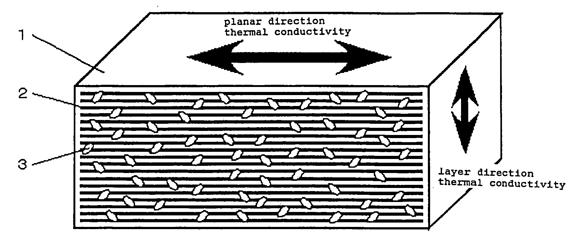
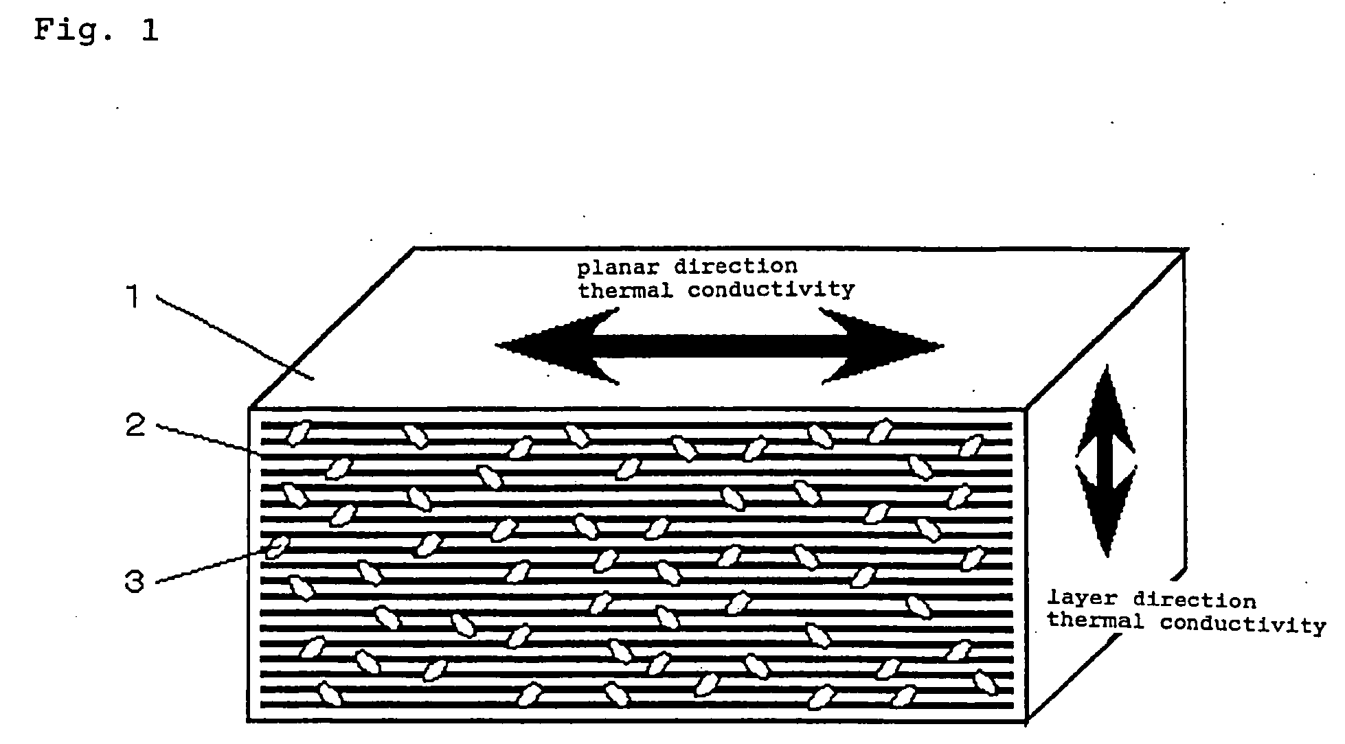
[0153]FIG. 1 is a simplified diagram of the high thermal conductive element in Embodiment 1 of the present invention.

[0154] The main constituent elements of this high thermal conductive element are a graphite structure 1 whose c axis is oriented substantially parallel to the thickness direction, and graphite particles 3 that are dispersed substantially uniformly in the graphite structure 1.

[0155] This graphite structure 1 consists of interdependently stacked graphene layers 2 composed of carbon six-membered ring structures, as mentioned above. Specifically, an inherent property of graphite is that the graphene layers are not merely stacked, but are stacked in predetermined positions (see FIG. 4), and this positional relationship is maintained in the stacking.

[0156] It is preferable to use a graphite structure (graphite-based matrix) 1 with which evaluation by X-ray diffraction reveals a interplanar spacing d within a range of d=0.335 to 0.340 nm, and in which the (002) plane and ...

embodiment 2

[0164] The above-mentioned graphite structure 1 can be produced by several methods, but from the standpoints of ease of production, characteristics of the resulting high thermal conductive element, and so forth, it is preferable to employ a method in which the graphite structure 1 is formed by heat-treating an organic polymer.

[0165] The method for obtaining a high thermal conductive element composed of a graphite structure by using an organic polymer as the starting raw material roughly comprises (I) a step of obtaining an organic polymer in which graphite particles are dispersed, and (II) a step of heat-treating the obtained product to graphitize the organic polymer.

[0166] With the present invention, a polyimide can be used favorably as the organic polymer, for example. When the goal is a polyimide as the organic polymer, polyamic acid, which is a polyimide precursor, can be used as the raw material. In view of this, this method will be described as an example in Embodiment 2.

[0...

embodiment 3

[0178] As discussed in Embodiment 2 above, the high thermal conductive element of the present invention can be produced by using a pre-graphitized material as the carbon particles. In contrast, in Embodiment 3, the high thermal conductive element of the present invention is manufactured by pre-blending a precursor of carbon as the raw material for the carbon particles, then simultaneously graphitizing this precursor in the course of graphitizing the matrix in the above-mentioned step II, and dispersing the graphite particles in the graphite structure. An example of this will be described in this Embodiment 3.

[0179] The basic production steps may be the same as in Embodiment 2.

[0180] In step I, an organic polymer that is a precursor of carbon is mixed and dispersed in a first organic polymer solution dissolved in a solvent, and this product is put in a specific shape, after which the solvent is volatilized to solidify the material, and a dehydration reaction is conducted by heating...


PUM

PropertyMeasurementUnit
Temperatureaaaaaaaaaa

Abstract

It is an object of the present invention to provide a high thermal conductive element that has improved thermal conductivity in the layer direction while retaining the high thermal conductivity characteristics in the planar direction possessed by graphite. The present invention is a high thermal conductive element in which carbon particles are dispersed in a graphite-based matrix, wherein (1) the c axis of the graphene layers constituting the graphite are substantially parallel, (2) the thermal conductivity κ∥ in a direction perpendicular to the c axis is at least 400 W/m·k and no more than 1000 W/m·k, and (3) the thermal conductivity κ⊥ in a direction parallel to the c axis is at least 10 W/m·k and no more than 100 W/m·k.

Description

FIELD OF THE INVENTION [0001] This invention relates to a high thermal conductive element whose main component is carbon (C), and to a method for manufacturing this member. The present invention further relates to a heat radiating system (heat radiating apparatus) that includes this high thermal conductive element. [0002] More specifically, the present invention relates to an improved thermally conductive member composed of a graphite structure having anisotropy in its degree of thermal conductivity, wherein this high thermal conductive element has relatively high thermal conductivity in its c axial direction while also retaining high thermal conductivity in a direction perpendicular to the c axial direction. BACKGROUND ART OF THE INVENTION [0003] As the performance and density of electronic devices have risen in recent years, while the size of these devices has decreased, an issue has been how to efficiently radiate the heat generated from these devices and the electronic component...

Claims


Application Information

Patent Timeline
IPC IPC(8): B32B9/00C08K3/04C04B35/52H01L23/373
CPCB82Y30/00Y10T428/30C04B35/63468C04B2235/422C04B2235/425C04B2235/427C04B2235/48C04B2235/526C04B2235/5284C04B2235/5436C04B2235/5445C04B2235/6562C04B2235/6565C04B2235/6567C04B2235/77C04B2235/78C04B2235/80C04B2235/9607H01L23/3733H01L2924/0002C04B35/522H01L2924/00
Inventor OZAKI, TOYOKAZUTAOMOTO, AKIRAHASHIMOTO, MITSURUDEGUCHI, MASAHIROSHIBATA, MOTOSHI
Owner PANASONIC CORP
Why Eureka
Try Eureka