
Lithium rechargeable battery and lithium rechargeable battery pack

Inactive Publication Date: 2006-02-16
SAMSUNG SDI CO LTD
View PDF5 Cites 91 Cited by
  • Summary
  • Abstract
  • Description
  • Claims
  • Application Information

AI Technical Summary

Benefits of technology

[0009] The present invention provides a lithium rechargeable battery that prevents dissolution of the negative current collector at over-discharge and does not require an over-discharge protection circuit. This allows the lithium rechargeable battery to be fabricated at a low-cost.

Problems solved by technology

When an electronic device malfunctions or uses a battery that has a cut-off voltage that is not set for the electronic device, open circuit voltage (OCV) is not restored even though a circuit is open when a discharge voltage is 0 V. Then when the battery is charged and discharged, the battery capacity may deteriorate significantly and may result in an internal short-circuit.
Performance deterioration and shortening of cycle-life upon over-discharge result from dissolution of copper from the negative current collector.
However, these conventional lithium rechargeable batteries require a means to install the over-discharge protection circuit.

Method used


Image

  • Lithium rechargeable battery and lithium rechargeable battery pack

Examples


example 1

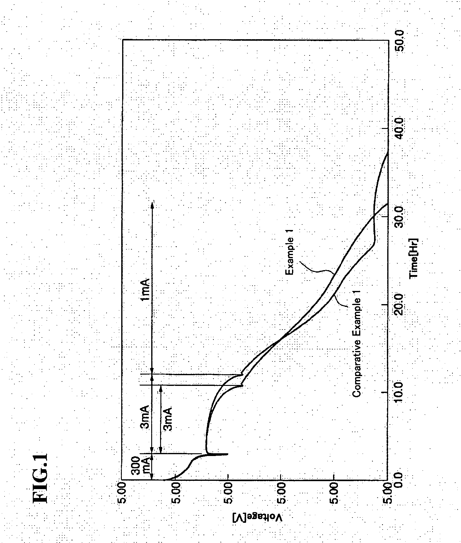
[0036] LiCoO2 with an average particle diameter of 10 μm as a positive active material, polyvinylidene fluoride as a binder, and carbon powders having an average particle diameter of 3 μm as a conducting agent were mixed. This mixture was then combined with N-methyl-2-pyrrolidone to prepare a positive electrode slurry. The positive electrode slurry was coated onto a 20 μm thick aluminum foil as a positive current collector and then dried at 120° C. for 24 hours under vacuum, thereby volatilizing N-methyl-2-pyrrolidone. The resulting coated positive current collector was then compressed to form a positive electrode.

[0037] 95 parts by weight of artificial graphite with an average particle diameter of 15 μm and 5 parts by weight of polyvinylidene fluoride as a binder were mixed. The mixture was then combined with N-methyl-2-pyrrolidone to prepare a negative electrode slurry. The negative electrode slurry was coated onto a 14 μm thick Cu foil as a negative current collector and then dr...

example 2

[0046] A positive active material, a binder, and a conductive agent were coated on an Al foil as a positive current collector to fabricate a positive electrode in the same manner as in Example 1. A negative active material and a binder were coated on a Cu foil as a negative current collector to fabricate a negative electrode in the same manner as in Example 1.

[0047] 1.3 mol / L of LiPF6 was added to a solvent including ethylene carbonate (EC), γ-butyrolactone (GBL) and diethylcarbonate (DEC) mixed in a volume ratio of EC:GBL:DEC=30:50:50. In addition, 3 wt % of fluoroethylene carbonate (FEC) and 1 wt % to 10 wt % of succinonitrile were added. Subsequently, diacryl monomer as a material for forming a polymer electrolyte and a 2,2′-azo-bis(isobutyronitrile) polymerization initiator were added to prepare an electrolyte.

[0048] A polypropylene porous separator was interposed between the positive electrode and the negative electrode and spirally wound together to form an electrode assembl...

examples 3 to 5

[0049] Lithium polymer rechargeable battery cells were fabricated with the same method as in Example 2, except that the concentration of succinonitrile was changed as shown in the following Table 1.


PUM


Abstract

A lithium rechargeable battery includes a positive electrode that intercalates and deintercalates lithium and a negative electrode that intercalates and deintercalates lithium and has a current collector including Cu or a Cu alloy. In addition, the battery includes a separator interposed between the positive electrode and the negative electrode, and an electrolyte that transfers lithium ions.

Description

CROSS-REFERENCE TO RELATED APPLICATION [0001] This application claims priority to and the benefit of Japanese Application No. 2004-226620 filed with the Japanese Patent Office on Aug. 3, 2004 and Korean Patent Application No. 10-2005-0025912 filed with the Korean Intellectual Property Office on Mar. 29, 2005, which are hereby incorporated by reference for all purposes as if fully set forth herein. BACKGROUND OF THE INVENTION [0002] 1. Field of the Invention [0003] The present invention relates to a lithium rechargeable battery and a lithium rechargeable battery pack that has improved over-discharge characteristics. [0004] 2. Discussion of the Background [0005] Rechargeable batteries with a high power storage capacity are being developed to power small, high power electronic devices such as video cameras and portable stereos. Lithium rechargeable batteries may use carbonaceous materials as a negative active material and a lithium cobalt oxide (LiCoO2) as a positive active material. T...

Claims


Application Information

Patent Timeline
IPC IPC(8): H01M10/40H01M4/66H01M4/58H01M10/0525H01M10/0565H01M10/0567H01M10/0569H01M10/36
CPCH01M4/38H01M10/0525Y02E60/122H01M10/0567H01M10/0569H01M10/0565Y02E60/10
Inventor SHIMIZU, RYUICHIYAMAGUCHI, TAKITAROJUNG, CHEOL-SOOCHUNG, HYUN-JEICHANG, YOUNG-CHUL
Owner SAMSUNG SDI CO LTD
Learn More