Radiographic image conversion panel for mammography and method of manufacturing the same
a technology of radiographic image and conversion panel, which is applied in the direction of optical radiation measurement, fluorescence/phosphorescence, instruments, etc., can solve the problems of deterioration of sharpness of reproduced images or the like, low productivity, and complicated manufacturing processes, so as to reduce the distance from the stimulable phosphor layer, improve the quality of image recording, and improve the effect of moisture resistan
- Summary
- Abstract
- Description
- Claims
- Application Information
AI Technical Summary
Benefits of technology
Problems solved by technology
Method used
Image
Examples
first embodiment
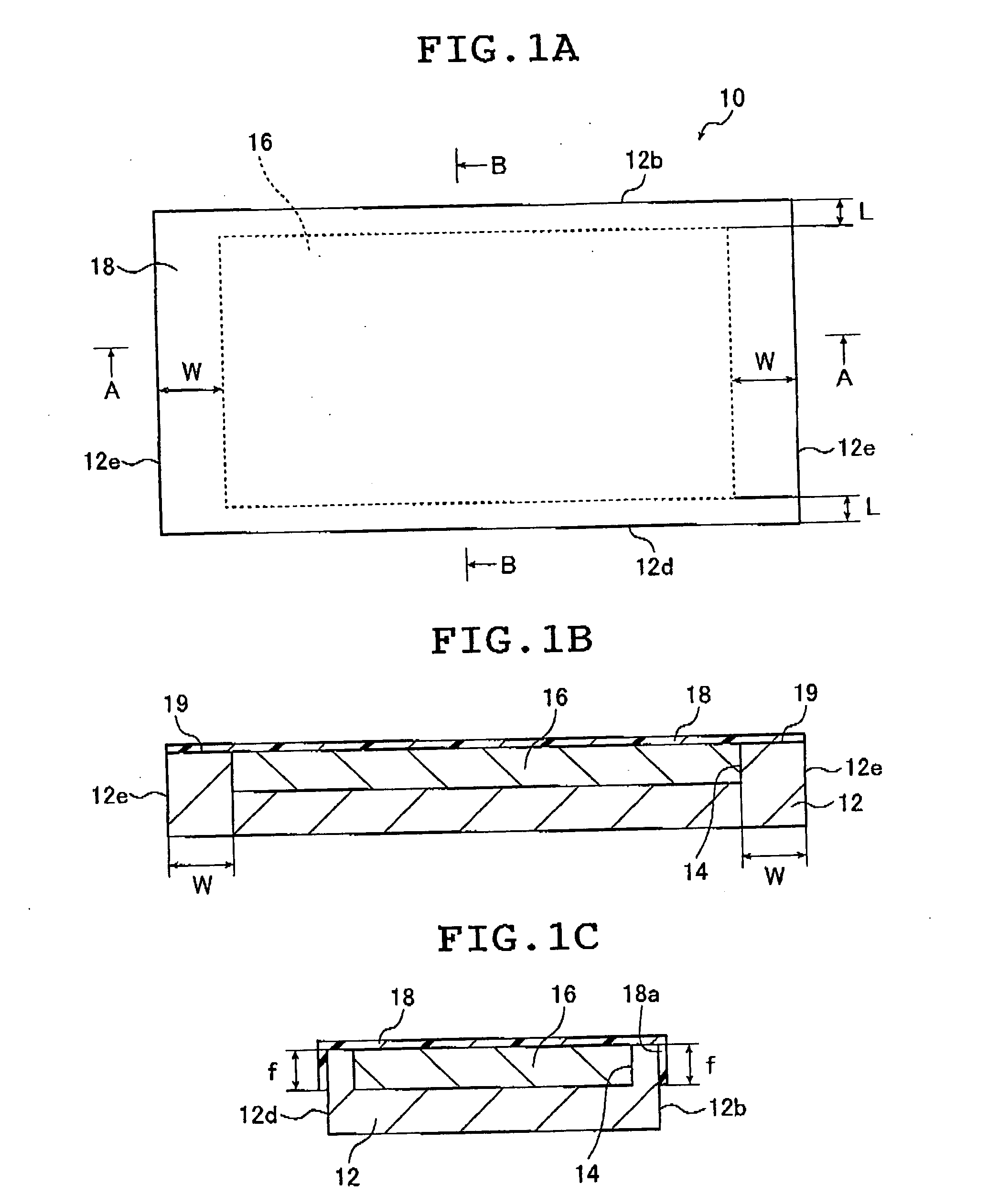
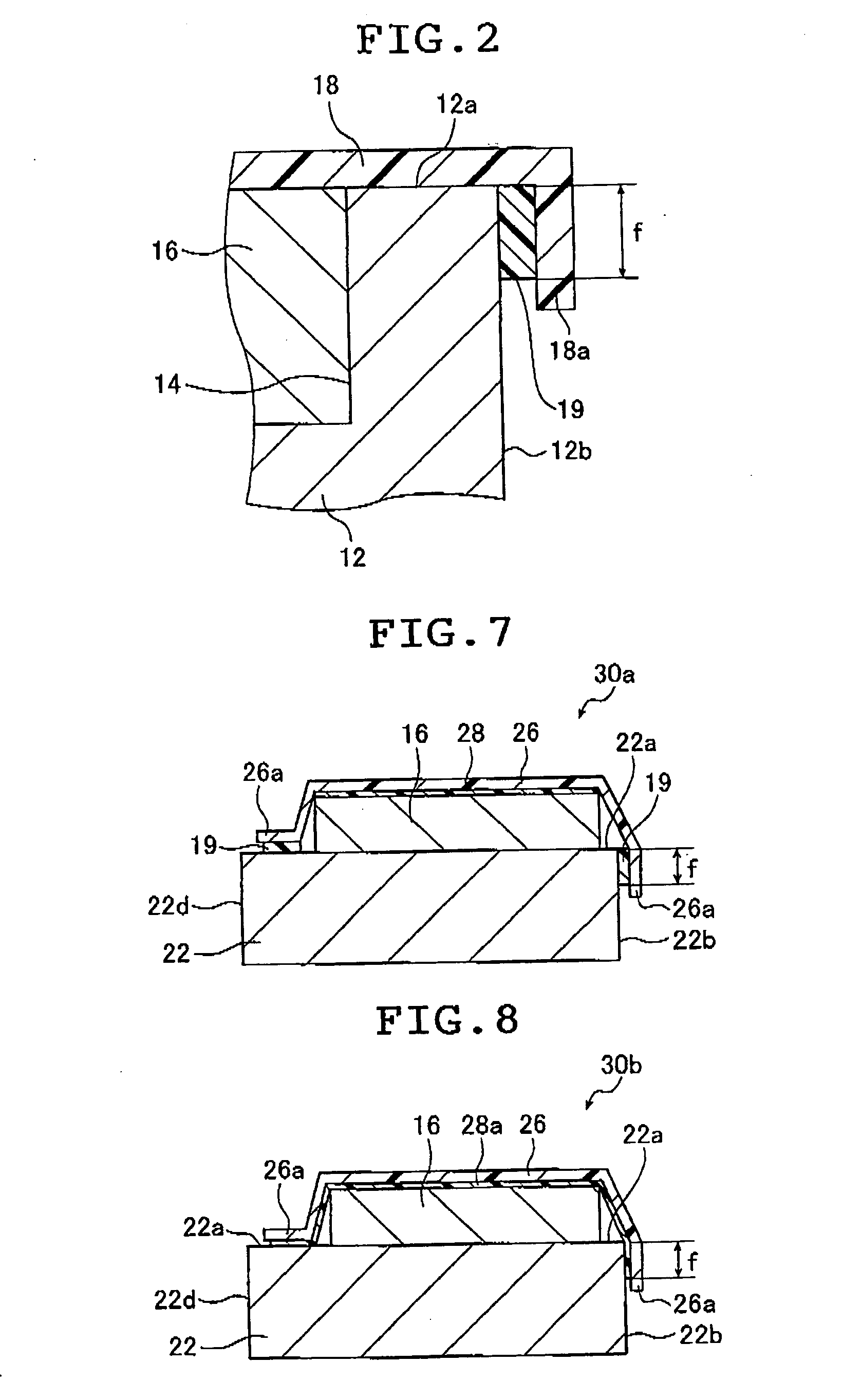
[0057]FIG. 1A is a schematic plan view showing a radiographic image conversion panel for mammography according to the present invention. FIG. 1B is a sectional view taken along the line A-A of FIG. 1A. FIG. 1C is a sectional view taken along the line B-B of FIG. 1A. FIG. 2 is an enlarged view of an essential part of FIG. 1C.
[0058] A radiographic image conversion panel (hereinafter referred to as phosphor panel) 10 for mammography shown in FIG. 1A is used in mammography with a side face 12b which includes one of two longer sides of a substrate 12, or a side face 12d which includes the other of the two longer sides of the substrate 12, facing toward the human body.
[0059] As shown in FIGS. 1A to 1C and FIG. 2, the phosphor panel 10 has the substrate 12, a stimulable phosphor layer (hereinafter referred to as phosphor layer) 16, a moisture-proof protective film 18, and a seal bonding layer 19 which bonds the perimeter of the moisture-proof protective film 18 to the substrate 12. A rece...
second embodiment
[0124] the present invention will be described next.
[0125]FIG. 3A is a schematic plan view showing a radiographic image conversion panel for mammography according to the second embodiment of the present invention. FIG. 3B is a sectional view taken along the line C-C of FIG. 3A. FIG. 3C is a sectional view taken along the line D-D of FIG. 3A. FIG. 4 is an enlarged view of an essential part of FIG. 3C.
[0126] In this embodiment, components corresponding to those of the phosphor panel 10 of the first embodiment shown in FIGS. 1A to 1C and FIG. 2 will be denoted by the same reference symbols and numerals, and the detailed description thereof will be omitted.
[0127] A phosphor panel 10a of this embodiment shown in FIGS. 3A to 3C differs from the phosphor panel 10 of the first embodiment (see FIGS. 1A to 1C) in terms of the position where the recess 14 is formed and the position where the moisture-proof protective film 18 is bonded to the substrate 12. The structure of the phosphor panel ...
third embodiment
[0143] the present invention will be described next.
[0144]FIG. 5 is a schematic sectional view showing a radiographic image conversion panel for mammography according to the third embodiment of the present invention, and corresponds to the sectional view taken along the line B-B of FIG. 1A. The seal bonding layer 19 is omitted in FIG. 5.
[0145] In this embodiment, components corresponding to those of the phosphor panel 10 of the first embodiment shown in FIGS. 1A to 1C and FIG. 2 will be denoted by the same reference symbols and numerals, and the detailed description thereof will be omitted.
[0146] A phosphor panel 20 of this embodiment differs from the phosphor panel 10 of the first embodiment in that no recess is formed in a substrate 22. The recess 14 is replaced by, for example, as shown in FIG. 5, a frame (sealing portion) 24 formed on a front face 22a of the substrate 22. The phosphor layer 16 is formed within the frame 24.
[0147] The frame 24 of this embodiment is formed arou...
PUM
 Abstract
Description
Claims
Application Information
 - R&D
- Intellectual Property
- Life Sciences
- Materials
- Tech Scout
- Unparalleled Data Quality
- Higher Quality Content
- 60% Fewer Hallucinations
Browse by: Latest US Patents, China's latest patents, Technical Efficacy Thesaurus, Application Domain, Technology Topic, Popular Technical Reports.
© 2025 PatSnap. All rights reserved.Legal|Privacy policy|Modern Slavery Act Transparency Statement|Sitemap|About US| Contact US: help@patsnap.com


