Light source unit and light irradiation unit

a technology of light irradiation unit and light source unit, which is applied in the direction of light demodulation, instrumentation, laser details, etc., can solve the problems of high running cost, complex maintenance operation, and inability to obtain sufficient wavelength conversion efficiency, and achieve the effect of improving wavelength conversion efficiency

Active Publication Date: 2006-02-23
NIKON CORP
View PDF12 Cites 39 Cited by
  • Summary
  • Abstract
  • Description
  • Claims
  • Application Information

AI Technical Summary

Benefits of technology

[0012] The present invention has been made under such circumstances, and its first obje

Problems solved by technology

However, such excimer lasers have their disadvantages as light source units, such as their large size, and their complicated maintenance operation and high running cost due to hazardous fluorine gas used.
However, the output level of the fundamental

Method used


Image

  • Light source unit and light irradiation unit
  • Light source unit and light irradiation unit
  • Light source unit and light irradiation unit

Examples


first embodiment

[0064] A first embodiment of the present invention will be described below, referring to FIGS. 1 to 9.

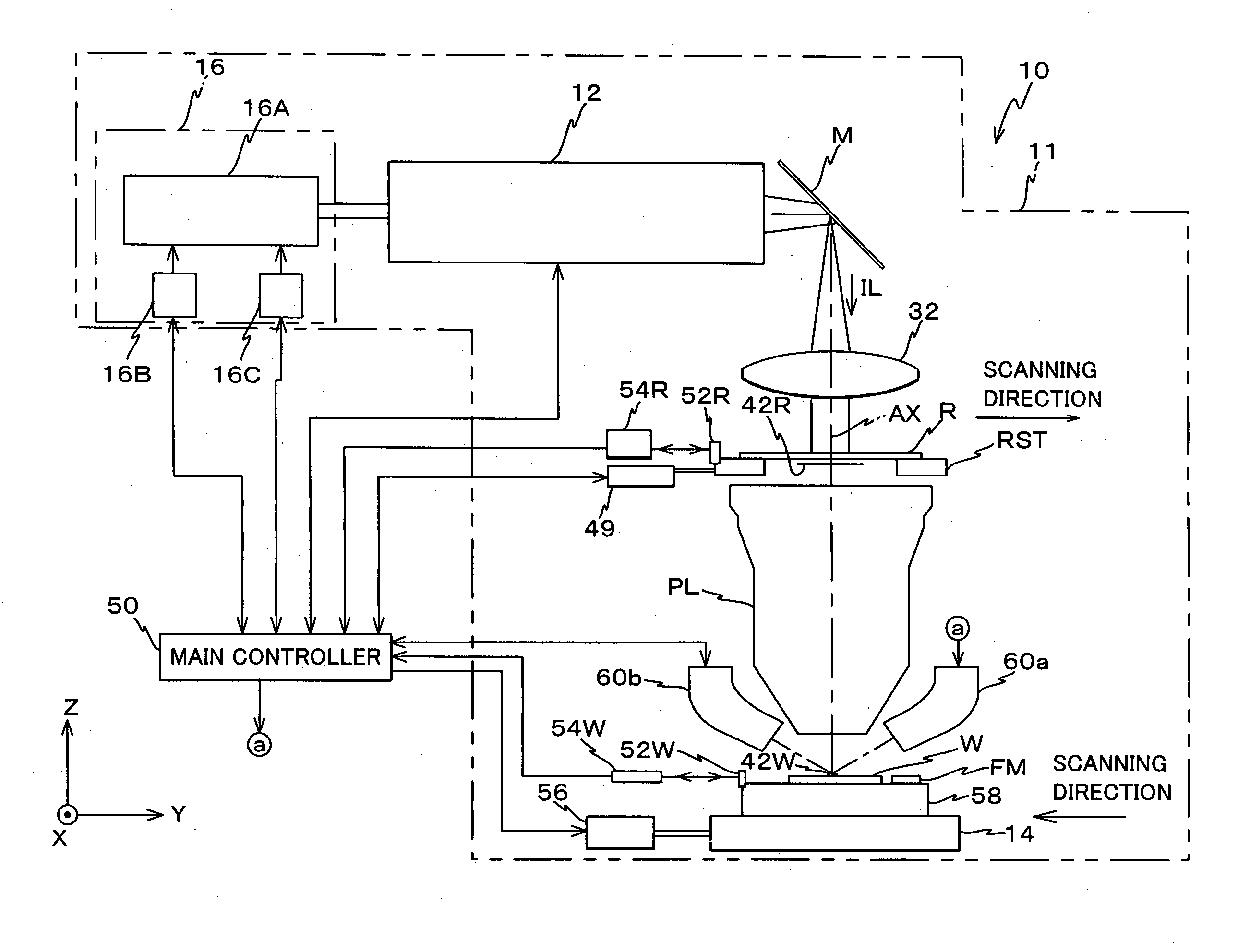
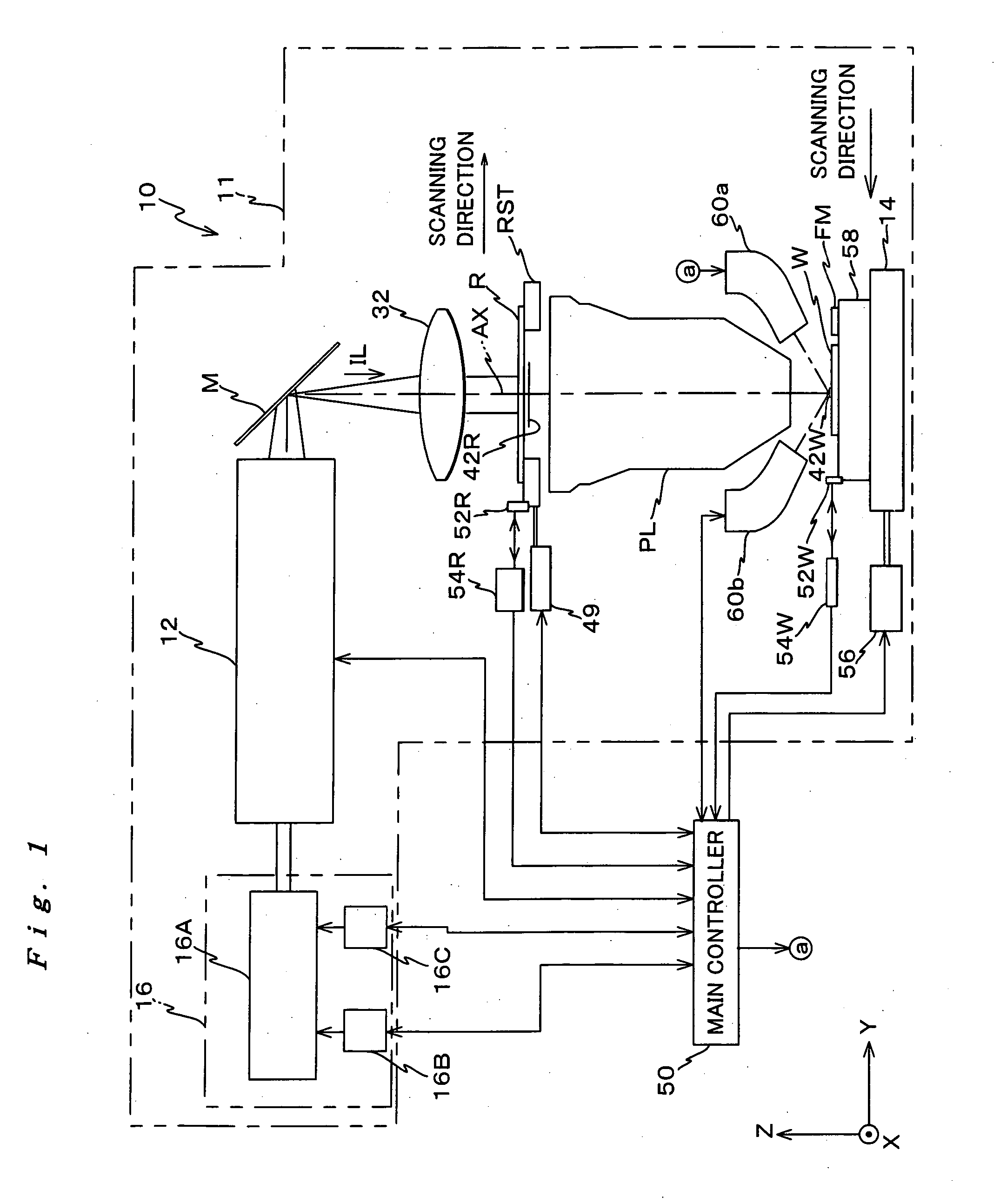
[0065]FIG. 1 shows a schematic structure of an exposure apparatus 10, which is a light irradiation unit related to the first embodiment being structured including a light source unit related to the present invention. Exposure apparatus 10 is a scanning exposure apparatus based on a step-and-scan method.

[0066] Exposure apparatus 10 comprises: an illumination system, which is made up of a light source unit 16 and an illumination optical system 12; a reticle stage RST that holds a reticle R serving as a mask, which is illuminated by an exposure illumination light (hereinafter referred to as “illumination light” or “exposure light”) IL emitted from the illumination system; a projection optical system PL that projects exposure light IL on a wafer W serving as a photosensitive object via reticle R; an XY stage 14 on which a Z-tilt stage 58 for holding wafer W is mounted, and a control s...

second embodiment

[0170] Next, a second embodiment of the present invention will be described referring to FIGS. 10 to 18. On describing the second embodiment, the reference numerals the same as those in the first embodiment will be used for the same or equivalent components, therefore, the description thereabout will be omitted.

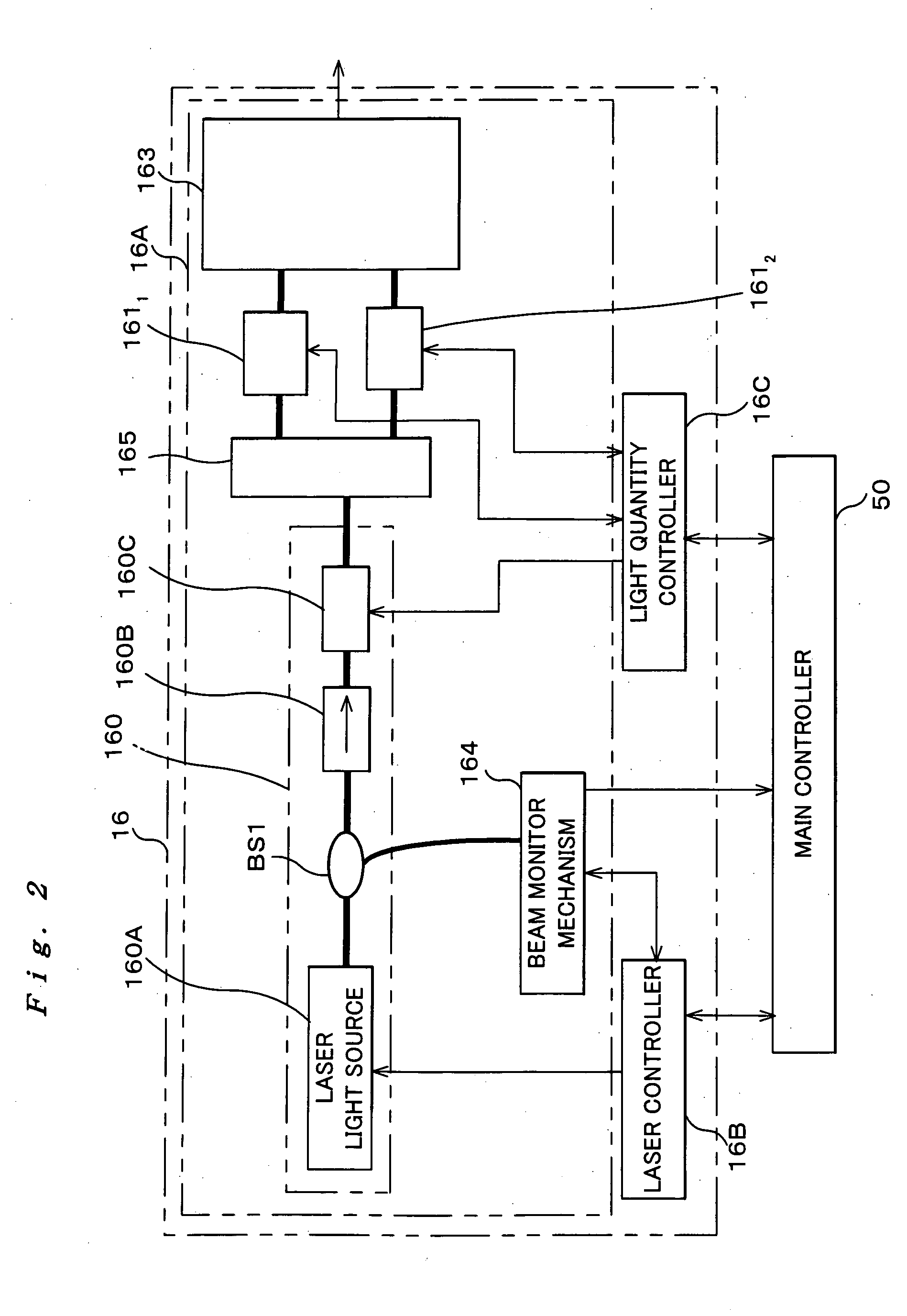
[0171] The exposure apparatus of the second embodiment differs from the exposure apparatus of the first embodiment on the point where the apparatus comprises a light source unit 16′ instead of light source unit 16. FIG. 10 schematically shows the configuration of light source unit 16′ related to the second embodiment. As is shown in FIG. 10, a light source section 16A′ of light source unit 16′ differs from light source section 16A of light source unit 16 shown in FIG. 2 on the point where light source 16A′ comprises a pulsed light generating section 190 in addition to pulsed light generating section 160 and it also newly comprises an optical amplifier 1911, instead of optica...


PUM


Abstract

In nonlinear optical crystal 183D, each step of wavelength conversion can be performed using another fundamental wave that is output from light output unit 1612, without using the fundamental wave whose output level has been attenuated after going through wavelength conversion for several steps (wavelength conversion in nonlinear optical crystals 183A to 183C). Therefore, the wavelength conversion efficiency improves and the peak power of optical amplifiers 1611 and 1612 can be suppressed, which allows the wavelength of lights that are output from optical amplifiers 1611 and 1612 to be further narrowed.

Description

BACKGOUND OF THE INVENTION [0001] 1. Field of The Invention [0002] The present invention relates to light source units and light irradiation units, more particularly to a light source unit that comprises a wavelength converter, which converts light having a single wavelength emitted from a laser light source into light having a different wavelength, and a light irradiation unit that comprises the light source unit. [0003] 2. Description of the Related Art [0004] Conventionally, light irradiation units have been used for fine structure inspection of objects, fine processing of objects, and for vision correction treatment. For example, in a lithographic process for manufacturing semiconductor devices or the like, in order to transfer a pattern formed on a mask or a reticle (hereinafter generally referred to as a “reticle”) onto a substrate such as a wafer on which a resist or the like is coated or a glass plate (hereinafter appropriately referred to as a “substrate” or a “wafer”) via ...

Claims


Application Information

Patent Timeline
IPC IPC(8): H01S3/10
CPCG02F1/353G03F7/70575G02F2001/354G02F1/354
Inventor TOKUHISA, AKIRAKITANO, HIROSHIKAWAI, HITOSHI
Owner NIKON CORP
Why Eureka
Try Eureka