Fuel cell

a fuel cell and solid oxide technology, applied in the field of solid oxide fuel cells, can solve the problems of reducing cell performance such as output and efficiency, difficult to maintain the temperature in the cell uniformly, damage to the cell, etc., and achieve the effect of preventing deterioration or corrosion of the cell material and increasing the cell outpu

Inactive Publication Date: 2006-02-23
HITACHI LTD
View PDF5 Cites 15 Cited by
  • Summary
  • Abstract
  • Description
  • Claims
  • Application Information

AI Technical Summary

Benefits of technology

[0008] The configuration may be such that the reforming catalyst is provided in the high-temperature portion in the cell reaction region of anode and further the combustion catalyst is provided in the low-temperature portion thereof. Also, by branchingly spraying an air flow from an air introduction tube of cathode so that a cooling effect is produced in the high-temperature portion, the temperature distribution can further be uniformed.
[0009] According to the present invention, the high-temperature portion in the cell reaction region of anode is cooled by the endothermic reaction of reforming catalyst, or the low-temperature portion in the cell reaction region of anode is heated by the exothermic reaction of combustion catalyst, so that the temperature distribution can be made uniform as the whole of the cell reaction region. As a result, effects of increased cell output, prevention of deterioration or corrosion of cell material, and the like can be achieved.

Problems solved by technology

The high cell working temperature of 600 to 1000° C. offers the above-described advantages, but on the other hand, has a disadvantage that it is very difficult to maintain the temperature in the cell uniformly.
Therefore, unevenness of cell current occurs, and the whole of the cell reaction region cannot be utilized uniformly, which corresponds to a decreased effective cell reaction area, so that the cell performance such as output and efficiency decreases.
Also, there arises a problem in that the cell is damaged by a thermal stress generated by a difference in temperature or the corrosion and degradation of material proceed in the high-temperature portion.

Method used


Image

  • Fuel cell
  • Fuel cell
  • Fuel cell

Examples


example 1

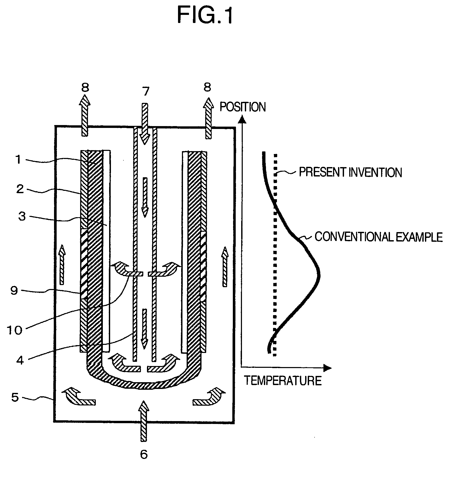
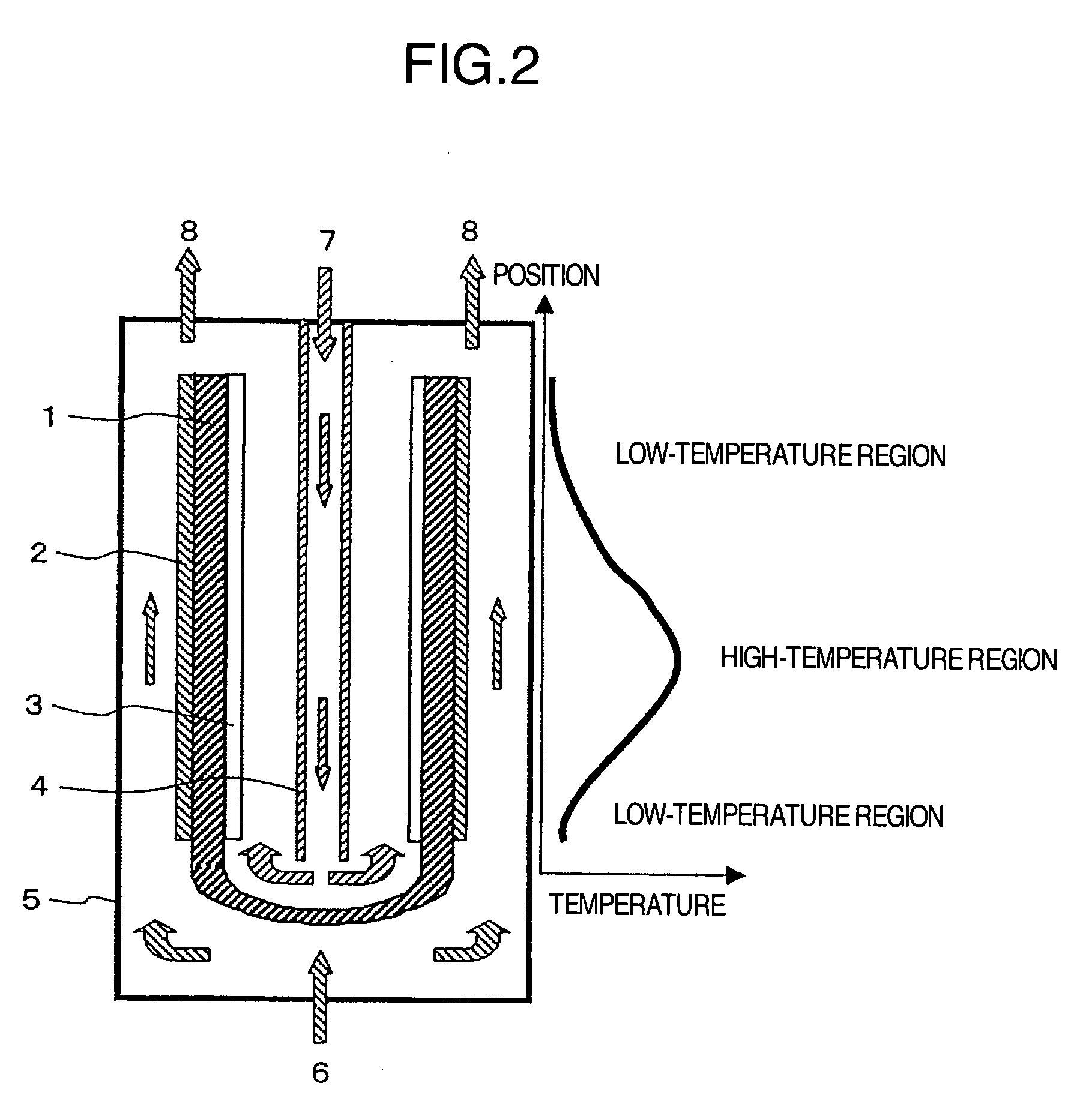
[0023]FIG. 1 shows an example in which the present invention is applied to a fuel cell having a tube type solid electrolyte. The fuel cell of this example is provided with the cathode 3 on the inner surface of the tube shaped solid electrolyte 1 and the anode 2 on the outer surface thereof, and is also provided with a reforming catalyst 9 in a high-temperature portion of the cell reaction region of the anode 2. Also, the air introduction tube 4 is provided in the inside space of the tube consisting of the solid electrolyte 1. The air introduction tube 4 is configured so that air is sprayed from two locations: the bottom portion of the tube and a location near the central portion in the axial direction of the electrolyte. As the solid electrolyte, yttrium-stabilized zirconia (YSZ) was used. As the anode 2, porous cermet consisting of nickel and YSZ was used, and as the cathode 3, lanthanum manganite was used. Also, as the reforming catalyst 9, a nickel-lanthanum based catalyst, which...

example 2

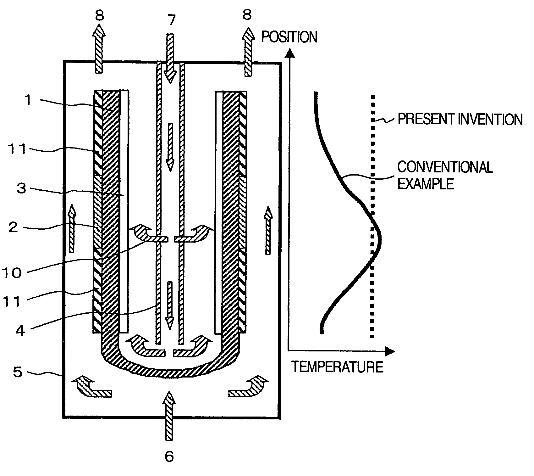
[0032]FIG. 3 shows another example of the present invention. In this example, after a combustion catalyst 11 was applied to the low-temperature portions of unit cell, namely, to the anode 2 corresponding to upper and lower positions in the axial direction of the tube shaped solid electrolyte 1, sintering was performed. As the combustion catalyst 11, a palladium-based catalyst can be used.

[0033] The combustion reaction of the combustion catalyst 11 is an exothermic reaction expressed by the following formula (5).

CH4+2O2→CO2+2H2O  (5)

[0034] For the unit cell of this example, the combustion catalyst 11 provided in the low-temperature portion of the anode 2 is heated, and thereby the temperatures in the upper and lower portions in the axial direction of the solid electrolyte 1 is increased. Therefore, the temperature distribution in the cell reaction region of anode can be made uniform as a whole in the axial direction of the electrolyte.

[0035] It is a matter of course that the meas...

example 3

[0036]FIG. 4 shows a still another example that is a modification of Example 1. In Example 1 shown FIG. 1, after the reforming catalyst 9 was applied to the anode 2 itself, sintering was performed. In Example 3 shown in FIG. 4, however, the reforming catalyst 9 was plasma sprayed on an electrode 12 provided at the outer periphery of the anode 2 to take out a current of the anode 2. The position at which the reforming catalyst 9 is provided is the same as that in Example 1, namely, a position corresponding to the central portion in the axial direction of the solid electrolyte 1. The function of the reforming catalyst is the same as that of the reforming catalyst shown in FIG. 1.

[0037]FIG. 5 shows a modification of Example 2. In Example 2 shown in FIG. 3, the combustion catalyst 11 was provided on the anode 2 itself. In this modification shown in FIG. 5, however, the combustion catalyst 11 was plasma sprayed on the electrode 12 provided at the outer periphery of the anode 2. The posi...


PUM

PropertyMeasurementUnit
temperatureaaaaaaaaaa

Abstract

In a solid oxide fuel cell, the nonuniformity of temperature distribution in the axial direction of a solid electrolyte, the decrease in cell performance caused by a decreased effective cell reaction area, and the damage to cell due to thermal stress generated by a temperature difference are restrained. A reforming catalyst is provided in a high-temperature portion on the anode side to cool the high-temperature portion by means of heat absorption of reforming reaction, or a combustion catalyst is provided in a low-temperature portion on the anode side to heat the low-temperature portion by means of heat generation of combustion reaction, or both of the catalysts are provided, by which the occurrence of variations in temperature in a cell reaction region of anode is prevented. In addition, an air flow from an air introduction tube of cathode is branchingly sprayed so that a cooling effect is produced in the high-temperature portion, by which an effect of restraining the variations in temperature can further be increased.

Description

BACKGROUND OF THE INVENTION [0001] The present invention relates to a fuel cell and, more particularly, to a solid oxide fuel cell. [0002] A fuel cell is a power generating device which is provided with an anode (fuel electrode) on one side and a cathode (air electrode) on the other side with an electrolyte being held therebetween, and generates power by allowing a fuel gas supplied to the anode side to react electrochemically with an oxidizer gas supplied to the cathode side via the electrolyte. A solid oxide fuel cell, which is one kind of fuel cells, not only has high power generating efficiency but also is operated at a high temperature of 600 to 1000° C., so that it can carry out a fuel reforming reaction in the cell without the use of a noble metal catalyst, and can use a variety of fuels. Also, since the cell system construction is simple, the solid oxide fuel cell has a potential for reducing the cost as compared with other types of fuel cells. Naturally, the exhaust heat is...

Claims


Application Information

Patent Timeline
Patent Type & Authority Applications(United States)
IPC IPC(8): H01M8/06H01M8/12
CPCH01M8/04007H01M8/04089H01M8/0637H01M8/0662Y02E60/525H01M8/1246H01M8/243Y02E60/521H01M8/1213Y02E60/50Y02P70/50
Inventor TOKOI, HIROMIKOBAYASHI, NARIYOSHITAKAHASHI, SHIN
Owner HITACHI LTD
Why Eureka
Try Eureka