Dual-plasma jet thruster with fuel cell

a fuel cell and thruster technology, applied in the direction of propulsive elements, cosmonautic components, cosmonautic parts, etc., can solve the problems of less efficiency and more physical space, and achieve the effect of less physical space, higher current density, and higher thrus

Inactive Publication Date: 2006-03-02
DAW SHIEN SCI RES & DEV
View PDF12 Cites 11 Cited by
  • Summary
  • Abstract
  • Description
  • Claims
  • Application Information

AI Technical Summary

Benefits of technology

[0021] An advantage of the present invention is that a higher thrust and higher current density of dual-plasma can be achieved, and therefore less physical space being needed.
[0022] Another advantage of the present invention is its scalability.
[0023] Yet another advantage of the present invention is the inclusion of an electric start system for providing a “warm-up” process for this unit. Before this unit is self-sustaining in replenishing the fuel, humidity, and oxygen, battery's power is provided to charge the plasmas and ignition system for generation of plasmas and thrust through a “C” shaped magnet.
[0024] Yet another advantage of the present invention is with no moving parts, thus no parts are subject to conventional wear and tear of sta

Problems solved by technology

In recent years, the conventional single plasma thrusters have generated a limited current density

Method used


Image

  • Dual-plasma jet thruster with fuel cell
  • Dual-plasma jet thruster with fuel cell
  • Dual-plasma jet thruster with fuel cell

Examples


Embodiment Construction

[0029] The advantages and the present invention will become better understood with referencing to the following more detailed descriptions and claims taken in conjunction with the accompanying drawings, in which like elements are identified with like symbols, and in which:

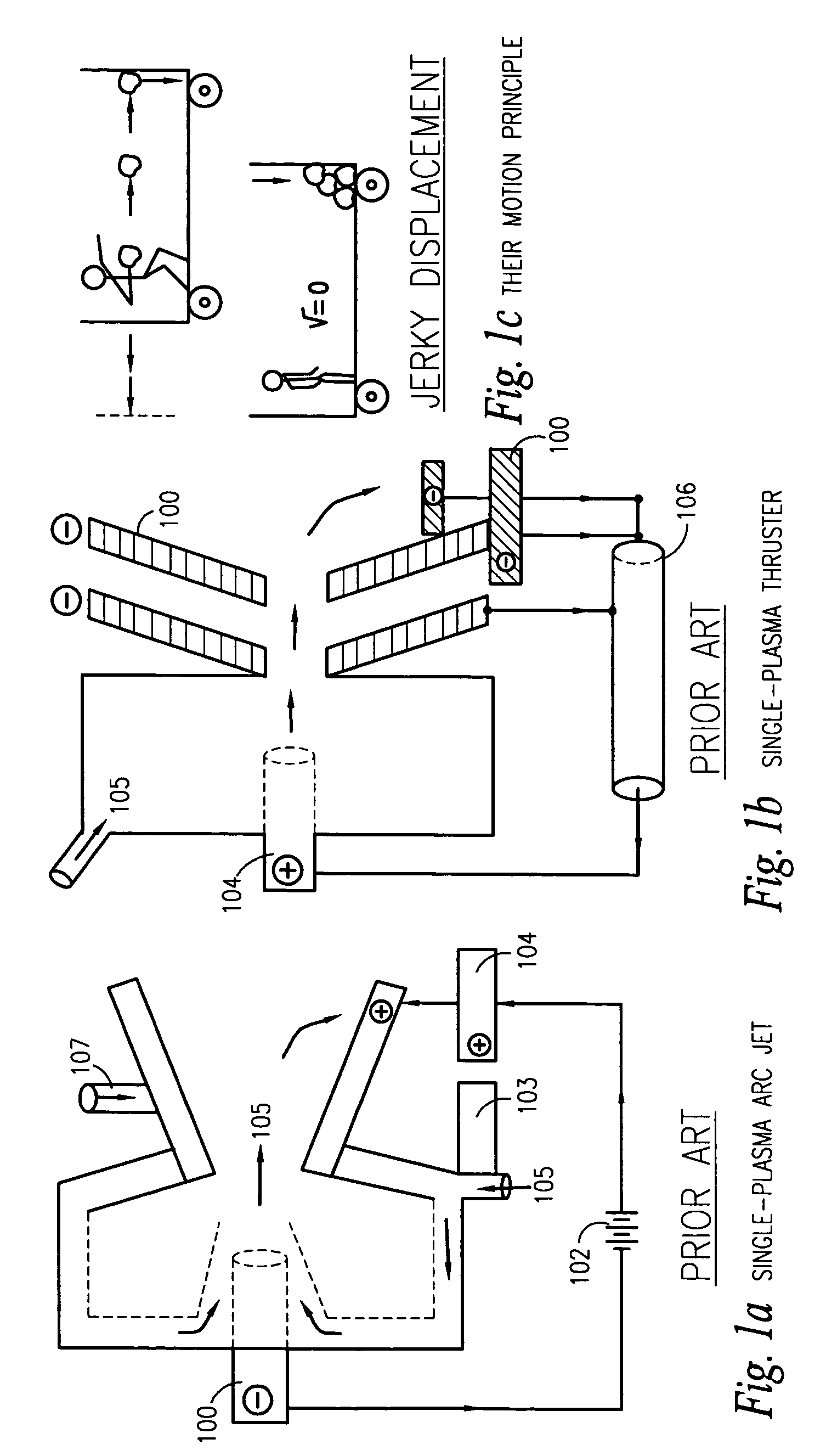
[0030]FIG. 1a is a schematic diagram of a conventional single (one) plasma arc jet according to the PRIOR ART;

[0031]FIG. 1b is a schematic diagram of a conventional single (one) plasma thruster according to the PRIOR ART;

[0032]FIG. 1c is a schematic illustration of the slowing abrupt (jerky) motion of a stationary car relative to balls thrown against a wall of throwing-catching effect within the same body;

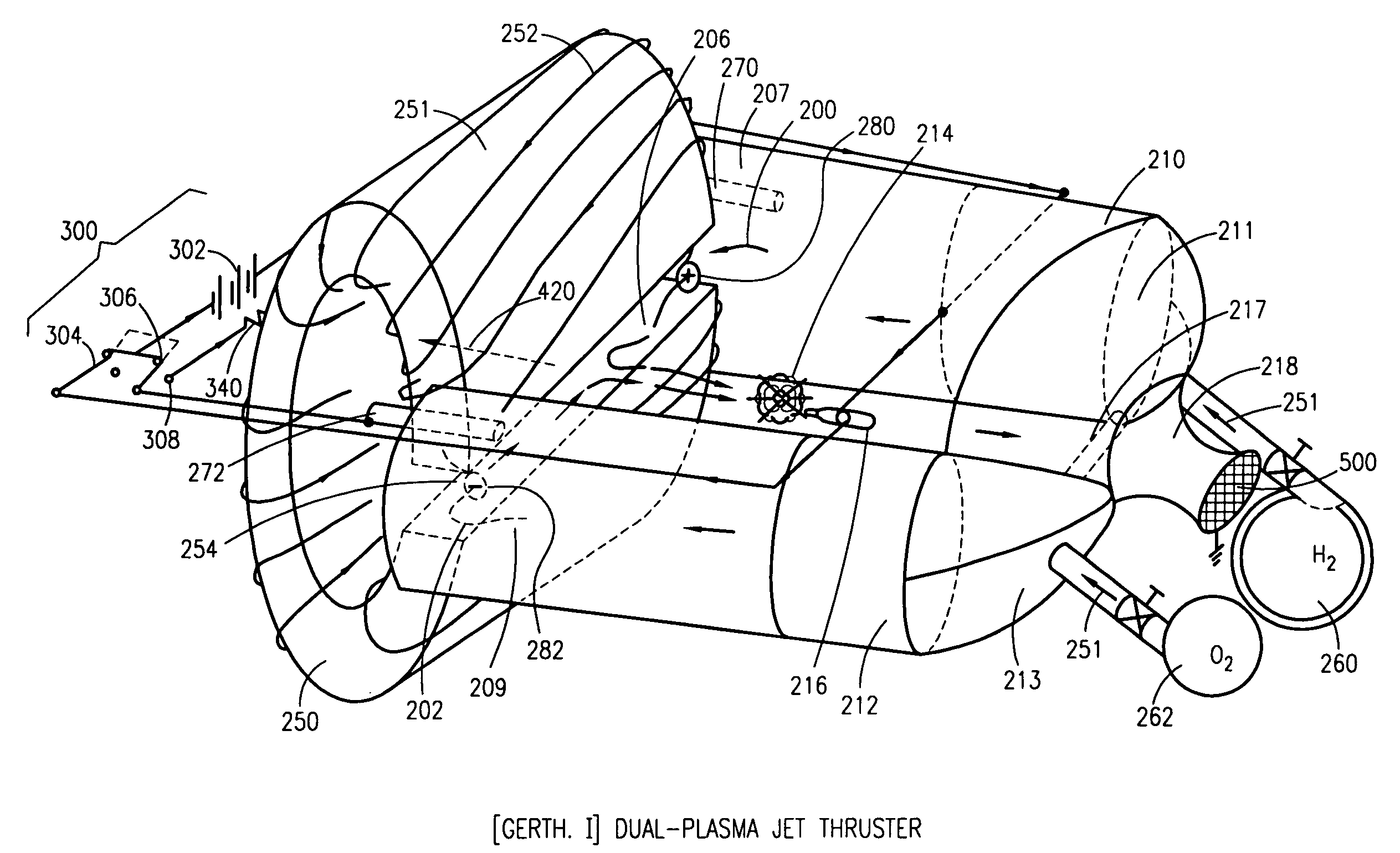
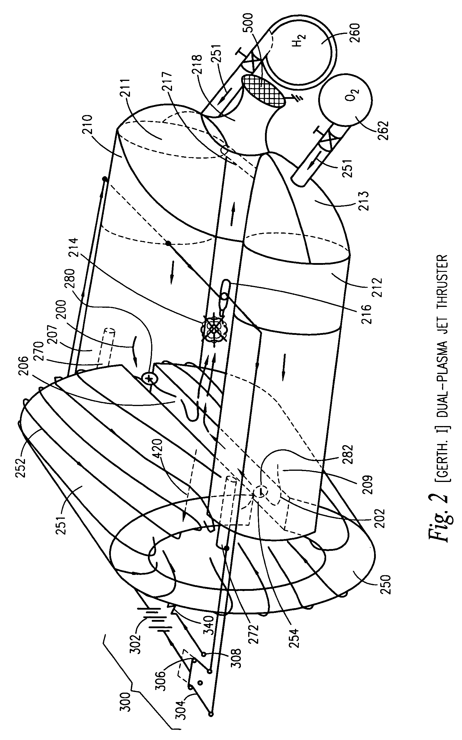
[0033]FIG. 2 is a schematic diagram of the First [GerTh. I] dual-plasma jet thruster (referred to as Thruster I) including an electric starter means; and

[0034]FIG. 3 is a schematic diagram of the Second electrified [DawShien. II] dual-plasma jet thruster (referred to as Thruster II) with utilizing saturated, ...


PUM


Abstract

New [GerTh. I]& [DawShien. II] dual-plasma jet thrusters provide the electric start system to start their warm-up processes, automatically. After their warm-up processes done and the operation temperatures reached, the [GerTh. I]& [DawShien. II] dual-plasma jet thrusters will run through themselves, independently by continuously supplying fuels and moisture into the units. Electrical power will be generated from the only [GerTh. I] jet thruster's fuel cell ([GOD, I] fuel cell) by thermal-plasmas reaction and then, its [GOD, I] fuel cell's fuel supplies are transformed from molecular forms into atomized and ionized forms by plasmas combustion heating, stepwise. When dual plasmas are ejected through the ‘C’ shaped magnet's opening sides, linear thrust is generated according to the right hand rule. Thereafter, the combustion and neutralization are conducted also with the same electric thrust direction for propelling the object in the same linear guided motion.

Description

BACKGROUND OF THE INVENTION [0001] 1. Field of the Invention [0002] The present invention relates generally to thermal-plasmas generation methods for power and, more particularly to a method of generating useful linear thrust with utilizing dual-plasma, positively and negatively charge-coupled plasmas which are passed through the latitudinal open end from opposite sides of a “C” shaped magnet, according to the right-hand rule, and combusted and neutralized in the combustion space thereafter to sustain their next processing cycle's heat and power demands. [0003] 2. Background of the Invention [0004] In recent years, the conventional single plasma thrusters have generated a limited current density with a slower jerky motion which results in the lower efficiency and requires more physical space. The dual-plasma thruster's (electro-thermal-chemical) process provides improvements and advantages over conventional thruster's problems of relating to the slow conversion of heat and chemical ...

Claims


Application Information

Patent Timeline
IPC IPC(8): F03H1/00
CPCF03H1/0025
Inventor SHIAO, JAMES SHIHFUSHIAO, ALBERT SHIH YUNG
Owner DAW SHIEN SCI RES & DEV
Why Eureka
Try Eureka