System and method for making nanoparticles using atmospheric-pressure plasma microreactor

a plasma microreactor and plasma technology, applied in the field of nanotechnology, can solve the problems of difficult production of blue-light emitting np-si and alter the emission characteristics, and achieve the effects of reducing the risk of coagulation, accelerating particle growth, and narrowing the size distribution

Inactive Publication Date: 2006-03-02
CALIFORNIA INST OF TECH
View PDF19 Cites 37 Cited by
  • Summary
  • Abstract
  • Description
  • Claims
  • Application Information

AI Technical Summary

Benefits of technology

[0017] Many benefits are achieved by way of the present invention over conventional techniques. For example, some embodiments of the present invention provide high-pressure microdischarges for the synthesis of nanometer-size silicon particles. For example, atmospheric-pressure microdischarges are used as short-residence time reactors for silicon nanoparticle synthesis. In one embodiment, the residence time of particle nucleation can be limited in the reactor to time scales on the order of milliseconds. In another example, charging of particles in plasma may prevent coagulation. In yet another example, high-pressure operation can accelerate particle growth.
[0018] Certain embodiments of the present invention can limit particle growth in the reaction zone allowing the production of ultrasmall nanoparticles with relatively narrow size distributions. For example, silicon nanoparticles are synthesized from a mixture of argon and silane in an atmospheric pressure plasma microreactor. Particles nucleate and grow to a f

Problems solved by technology

Many of these techniques involve a capping agent for protection from uncontrolled oxidation which, however, may introduce surface recombination states that alter the emission charac

Method used


Image

  • System and method for making nanoparticles using atmospheric-pressure plasma microreactor
  • System and method for making nanoparticles using atmospheric-pressure plasma microreactor
  • System and method for making nanoparticles using atmospheric-pressure plasma microreactor

Examples


Embodiment Construction

[0037] The present invention relates generally to the field of nanotechnology. More specifically, the invention provides a method and system for making nanoparticles using an atmospheric-pressure plasma microreactor. Merely by way of example, the invention has been applied to making silicon nanoparticles, but it would be recognized that the invention has a much broader range of applicability.

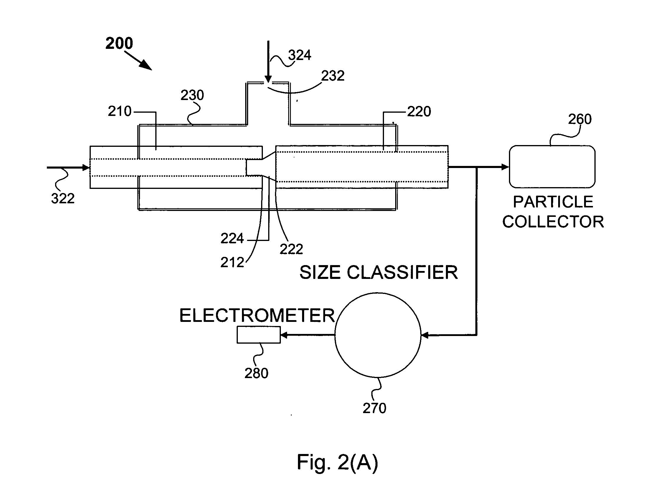
[0038] FIGS. 2(A) and 2(B) each show a simplified system for making silicon nanoparticles according to an embodiment of the present invention. These diagrams are merely examples, which should not unduly limit the scope of the claims. One of ordinary skill in the art would recognize many variations, alternatives, and modifications. A system 200 includes a cathode 210, an anode 220, a sealing tube 230, particle collector 260, a size classifier 270, and an electrometer 280. Although the above has been shown using a selected group of components for the system 200, there can be many alternatives, mo...


PUM

PropertyMeasurementUnit
Diameteraaaaaaaaaa
Diameteraaaaaaaaaa
Diameteraaaaaaaaaa

Abstract

A system and method for making nanoparticles. The system includes a first cathode including a first metal tube associated with a first end and a second end, a first anode including a second metal tube associated with a third end and a fourth end, and a first container including a first gas inlet. The first end and the third end are located inside the first container. The first end and the third end are separated by a first gap, the first metal tube is configured to allow a first gas to flow from the second end to the first end, and the first container is configured to allow a second gas to flow from the first gas inlet into the second metal tube through at least a first part of the first gap.

Description

CROSS-REFERENCES TO RELATED APPLICATIONS [0001] This application claims priority to U.S. Provisional No. 60 / 604,118 filed Aug. 24, 2004, which is incorporated by reference herein.STATEMENT AS TO RIGHTS TO INVENTIONS MADE UNDER FEDERALLY SPONSORED RESEARCH OR DEVELOPMENT [0002] Work described herein has been supported, in part, by NSF Grant No. CTS-0404353. The United States Government may therefore have certain rights in the invention. [0003] The following two commonly-owned co-pending applications, including this one, are being filed concurrently and the other one is hereby incorporated by reference in its entirety for all purposes: [0004] 1. U.S. patent application Ser. No. ______ , in the name of R. Mohan Sankaran, Konstantinos P. Giapis, Richard C. Flagan, and Dean Holunga, titled “System and Method for Making Nanoparticles Using Atmospheric-Pressure Plasma Microreactor” (Attorney Docket Number 020859-005010US); and [0005] 2. U.S. patent application Ser. No. ______ , in the name...

Claims


Application Information

Patent Timeline
IPC IPC(8): B22F9/16
CPCB01J19/0093B01J19/088B01J2219/00853B01J2219/083B01J2219/0875B01J2219/0894Y10S977/844B22F9/30B22F2999/00B22F9/14Y10S977/88
Inventor SANKARAN, R. MOHANGIAPIS, KONSTANTINOS P.FLAGAN, RICHARD C.HOLUNGA, DEAN
Owner CALIFORNIA INST OF TECH
Why Eureka
Try Eureka