

Manufacturing equipment of SiC Single crystal and method for manufacturing SiC single crystal
- Summary
- Abstract
- Description
- Claims
- Application Information
AI Technical Summary
Benefits of technology
Problems solved by technology
Method used
Image

Examples
first embodiment
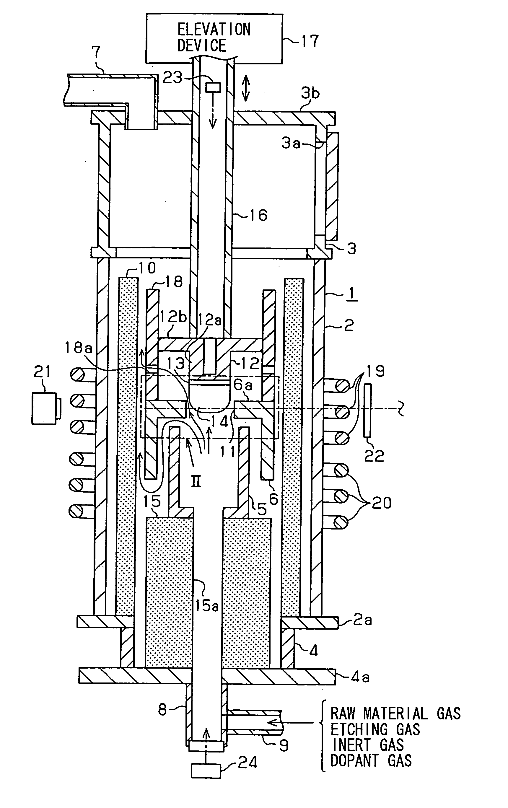
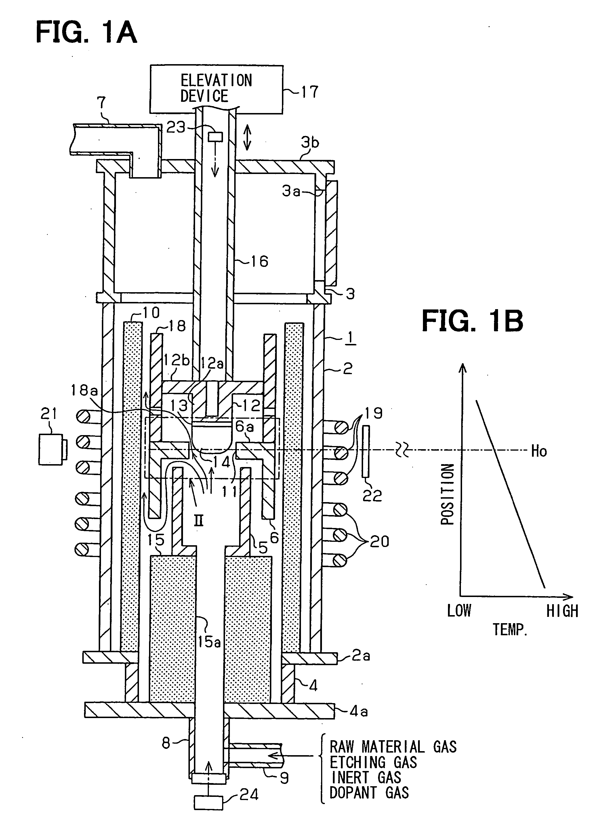
[0033] Manufacturing equipment of a SiC (silicon carbide) single crystal according to a first embodiment of the present invention is shown in FIGS. 1A and 2. FIG. 2 shows a main part of the equipment shown as II in FIG. 1A. The equipment performs to grow a SiC single crystal 14 from a seed crystal 13.
[0034] The equipment includes a vacuum chamber 1 having a cylindrical shape. The vacuum chamber 1 is composed of a main chamber 2, an upper chamber 3 and a lower chamber 4. The upper chamber 3 is disposed on the main chamber 2, and the lower chamber 4 is disposed under the main chamber 2. The inside of the main chamber 2, the inside of the upper chamber 3 and the inside of the lower chamber 4 are connected each other. A reaction chamber composed of a lower reaction chamber 5 and an upper reaction chamber 6 is disposed in the main chamber 2. A raw material gas is introduced into the reaction chamber through the lower chamber 4. Further, the SiC single crystal 14 after the crystal growth...
second embodiment
[0066] Manufacturing equipment for manufacturing a SiC single crystal according to a second embodiment of the present invention is shown in FIG. 6A. Although the equipment shown in FIG. 1 includes the X-ray generating equipment 21 and the image tube 22, the equipment shown in FIG. 6A includes an optical detector 30. The optical detector 30 measures amount of light passing through a guide hole 32 so that the optical detector 30 indirectly measures the diameter of the crystal 14. Specifically, the optical detector 30 indirectly measures a distance between the crystal 14 and the cover 6a by detecting leakage of the light. The optical detector 30 is fixed on the shaft 16. A slit 31 for observing the light is formed on the circular plate portion 12b of the base 12. The light to be observed is, for example, radiation light from the top of the cover 6a and radiation light from the reaction chambers 5, 6 passing through a clearance between the crystal 14 and the cover 6a. The radiation ligh...
third embodiment
[0096] Manufacturing equipment according to a third embodiment of the present invention is shown in FIG. 15. The base 12 includes the columnar portion 12a and the circular plate portion 12b. The circular plate portion 12b is formed on one end of the columnar portion 12a. The diameter of the circular plate portion 12b is larger than that of the columnar portion 12a. The seed crystal 13 is fixed on the bottom of the circular portion 12a. The diameter of the columnar portion 12a is almost the same as the seed crystal 13 and the SiC single crystal 14. The seed crystal 13 is bonded to the bottom of the columnar portion 12a with an adhesive.
[0097] The base 12 is capable of sliding in such a manner that the outer surface of the circular plate portion 12b contacts the inner surface of the cylindrical member 18. Thus, the base slides in the vertical direction with adhering and contacting the cylindrical member 18. The base 12 is pulled up so that the sliding direction of the base 18 is oppo...
PUM
 Abstract
Description
Claims
Application Information