Method for reactive sputter deposition of a magnesium oxide (MgO) tunnel barrier in a magnetic tunnel junction

a magnesium oxide and tunnel barrier technology, applied in the field of mtj devices, can solve the problems of mtjs fabricated, loss of magnetic moment at the interface of cofe ferromagnetic film and mgo tunnel barrier, and undesirable high resistance (r) and low tunneling magnetoresistance (tmr)

Inactive Publication Date: 2006-03-02
HITACHI GLOBAL STORAGE TECH NETHERLANDS BV
View PDF31 Cites 66 Cited by
  • Summary
  • Abstract
  • Description
  • Claims
  • Application Information

AI Technical Summary

Benefits of technology

[0014] The invention is a method for reactive sputter deposition of a magnesium oxide (MgO) tunnel barrier onto an iron-containing film. The method is part of the fabrication of a MTJ and the iron-containing film is the lower ferromagnetic film in the MTJ. The MgO tunnel barrier is sputter deposited from a Mg target in the presence of reactive oxygen (O2) gas in the “high-voltage” state to assure that deposition occurs with the Mg target in its metallic mode, i.e., no or minimal oxidation.

Problems solved by technology

This results in a loss of magnetic moment at the interface of the CoFe ferromagnetic film and the MgO tunnel barrier.
The MTJs fabricated in this state thus have undesirable high resistance (R) and low tunneling magnetoresistance (TMR).
A decrease in the target voltage indicates the beginning of oxidation of the target, which is undesirable.
However, it is best to avoid deposition as the target begins to be “poisoned” because the deposition rate is changing rapidly in the poisoning phase, making MgO thickness control difficult.

Method used


Image

  • Method for reactive sputter deposition of a magnesium oxide (MgO) tunnel barrier in a magnetic tunnel junction
  • Method for reactive sputter deposition of a magnesium oxide (MgO) tunnel barrier in a magnetic tunnel junction
  • Method for reactive sputter deposition of a magnesium oxide (MgO) tunnel barrier in a magnetic tunnel junction

Examples


Embodiment Construction

Prior Art

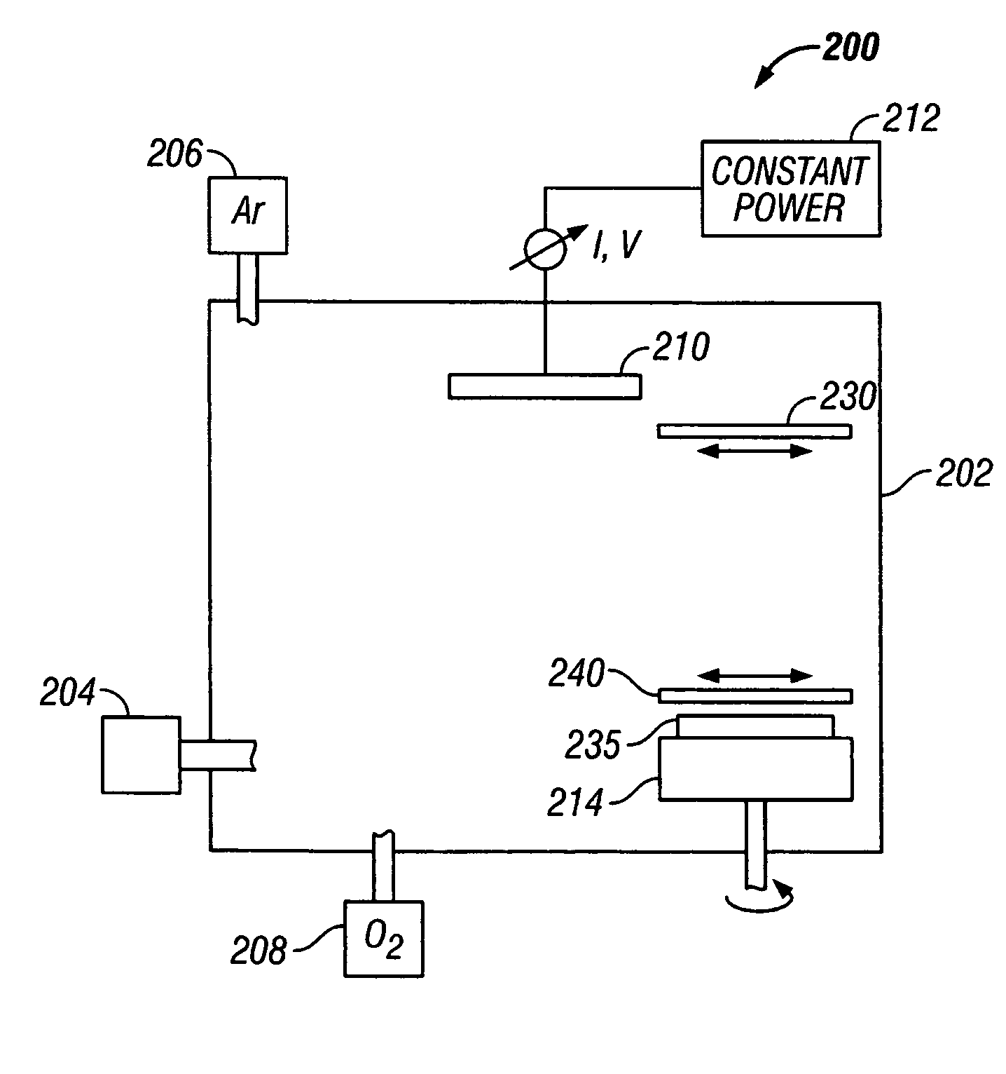
[0026] The method of this invention has application to the formation of the tunnel barrier required for a MTJ read head. The MTJ read head has application for use in a magnetic recording disk drive, the operation of which will be briefly described with reference to FIGS. 1-3.

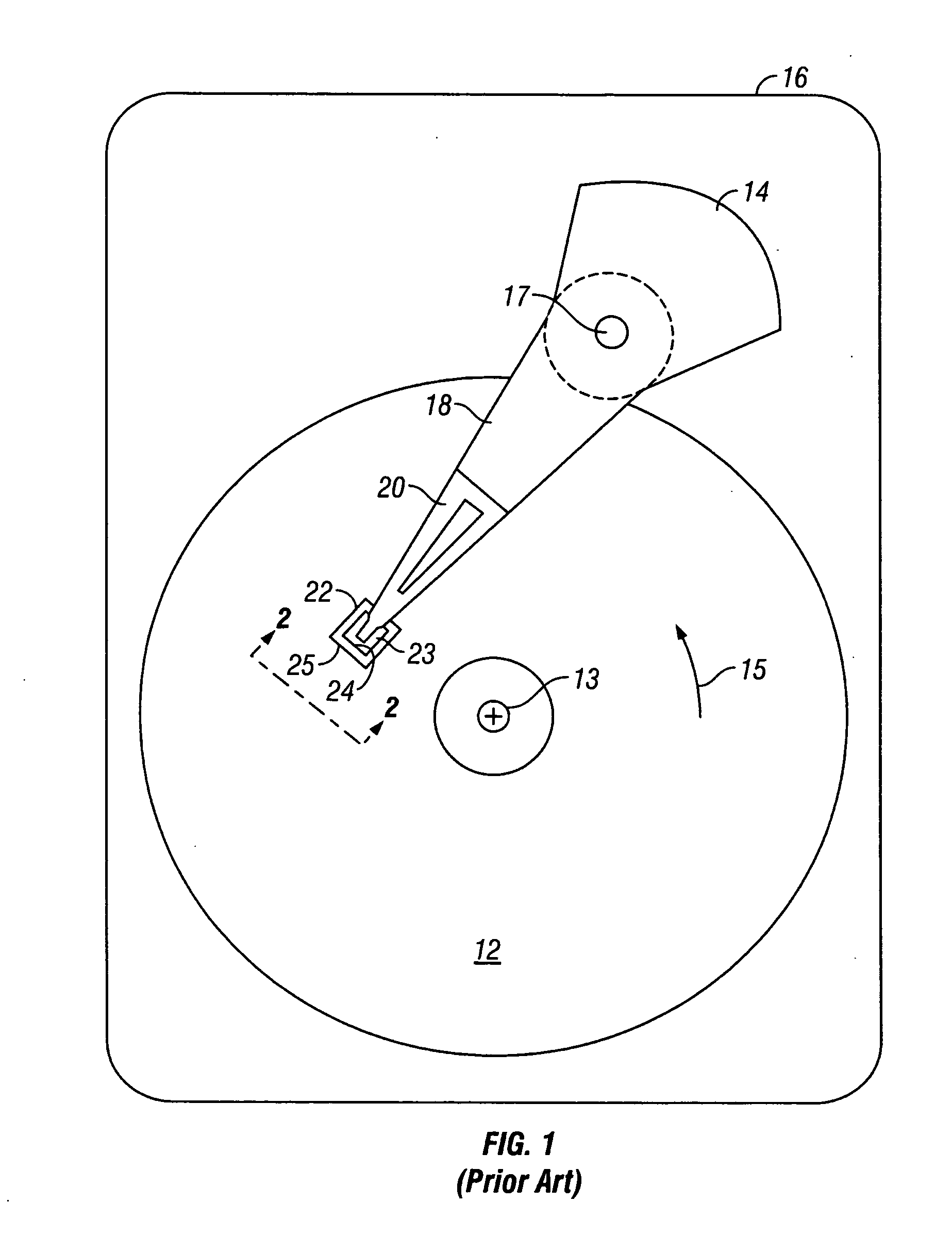
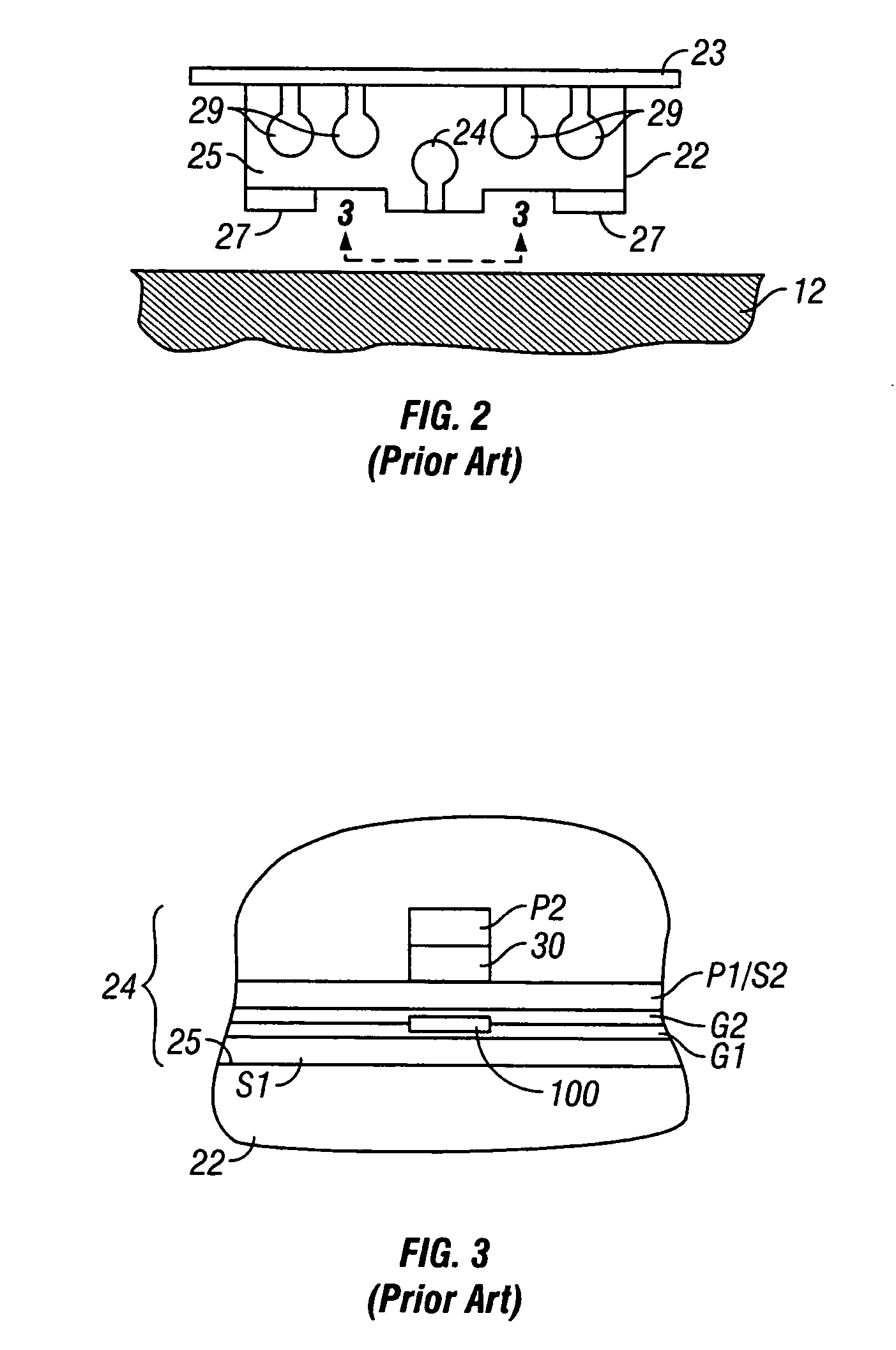
[0027]FIG. 1 is a block diagram of a conventional magnetic recording hard disk drive 10. The disk drive 10 includes a magnetic recording disk 12 and a rotary voice coil motor (VCM) actuator 14 supported on a disk drive housing or base 16. The disk 12 has a center of rotation 13 and is rotated in direction 15 by a spindle motor (not shown) mounted to base 16. The actuator 14 pivots about axis 17 and includes a rigid actuator arm 18. A generally flexible suspension 20 includes a flexure element 23 and is attached to the end of arm 18. A head carrier or air-bearing slider 22 is attached to the flexure 23. A magnetic recording read / write head 24 is formed on the trailing surface 25 of slider 22. The flex...


PUM

PropertyMeasurementUnit
voltage stateaaaaaaaaaa
timeaaaaaaaaaa

Abstract

As part of the fabrication of a magnetic tunnel junction (MTJ), a magnesium oxide (MgO) tunnel barrier is reactively sputter deposited from a Mg target in the presence of reactive oxygen gas (O2) in the “high-voltage” state to assure that deposition occurs with the Mg target in its metallic mode, i.e., no or minimal oxidation. Because the metallic mode of the Mg target has a finite lifetime, a set of O2 flow rates and associated sputter deposition times are established, with each flow rate and deposition time assuring that deposition occurs with the Mg target in the metallic mode and resulting in a known tunnel barrier thickness. The commencement of undesirable Mg target oxidation is associated with a decrease in target voltage, so the sputtering can also be terminated by monitoring the target voltage and terminating application of power to the target when the voltage reaches a predetermined value.

Description

RELATED APPLICATION [0001] This application is related to concurrently filed application Ser. No. ______ filed ______, 2004 and titled “METHOD FOR REACTIVE SPUTTER DEPOSITION OF AN ULTRA-THIN METAL OXIDE FILM” (Attorney Docket No. HSJ920040149US1).BACKGROUND OF THE INVENTION [0002] 1. Field of the Invention [0003] This invention relates generally to magnetic tunnel junction (MTJ) devices, and more particularly to a method for forming a magnesium oxide (MgO) tunnel barrier in a MTJ. [0004] 2. Description of the Related Art [0005] A magnetic tunnel junction (MTJ) is comprised of two layers of ferromagnetic material separated by a thin insulating tunnel barrier. The tunnel barrier is sufficiently thin that quantum-mechanical tunneling of the charge carriers occurs between the ferromagnetic layers. The tunneling process is electron-spin-dependent, which means that the tunneling current across the junction depends on the spin-dependent electronic properties of the ferromagnetic materials...

Claims


Application Information

Patent Timeline
Patent Type & Authority Applications(United States)
IPC IPC(8): C23C14/00
CPCB82Y25/00B82Y40/00C23C14/0036C23C14/025C23C14/081C23C14/34H01F10/3295G11C11/16H01F10/3254H01F41/18H01F41/307H01F41/32H01L43/12G11B5/3903H10N50/01
Inventor MAURI, DANIELE
Owner HITACHI GLOBAL STORAGE TECH NETHERLANDS BV
Why Eureka
Try Eureka