
Optical amplification device, raman amplifier, optical wavelength-division multiplex transmission system and optical wavelength-division multiplex transmission method

Inactive Publication Date: 2006-03-02
FUJITSU LTD
View PDF8 Cites 11 Cited by
  • Summary
  • Abstract
  • Description
  • Claims
  • Application Information

AI Technical Summary

Benefits of technology

[0013] It is an object of the present invention to provide an amplification technology capable of accurately detecting the interruption of signal light, without being affected by the increase / decrease of the number of wavelengths to be used, in an optical transmission line for wavelength-division multiplex communication.
[0014] It is another object of the present invention to provide an amplification technology capable of precisely performing a variety of control, based on the level determination of signal light.
[0020] According to the above-mentioned present invention, noise light in the wavelength range out of a band for signal light corresponding to the relevant number of wavelengths can be eliminated, according to the increase / decrease of the number of wavelengths to used. Therefore, if a wavelength-division multiplex communication is operated using a fairly small number of signal light, the fact that since signal light is buried in noise light, such as ASE, ASS or the like, the level of signal light cannot be determined by a threshold value, is surely avoided.
[0021] As a result, the interruption of signal light can be accurately detected without being affected by the increase / decrease of the number of wavelengths to be used.

Problems solved by technology

Therefore, the detection accuracy of main signal interruption and the accuracy of total power control have been remarkably degraded.
However, in the case of a small number of wavelengths when only a part of signal light is used, as shown in the right of FIG. 1, a ratio of the level of noise light to the total level of signal light becomes large, and it becomes difficult to control errors by the level determination by threshold of signal light.
Therefore, even when the input of signal light is interrupted by the disconnection of a transmission line fiber or the like, the amount of noise light does not drop below the threshold value, and accordingly, sometimes signal interruption can not be detected, and the automatic power shutdown of excitation light output could not function.
However, in this case, since an optical filter must be installed in addition to an amplifier, a structure becomes complex.
However, in Patent reference 2, the above-mentioned problem in the case where spontaneously emitted light and a plurality of segments of signal light are mixed is not recognized.

Method used


Image

  • Optical amplification device, raman amplifier, optical wavelength-division multiplex transmission system and optical wavelength-division multiplex transmission method
  • Optical amplification device, raman amplifier, optical wavelength-division multiplex transmission system and optical wavelength-division multiplex transmission method
  • Optical amplification device, raman amplifier, optical wavelength-division multiplex transmission system and optical wavelength-division multiplex transmission method

Examples


Embodiment Construction

[0039] The preferred embodiments of the present invention are described in detail below with reference to the drawings.

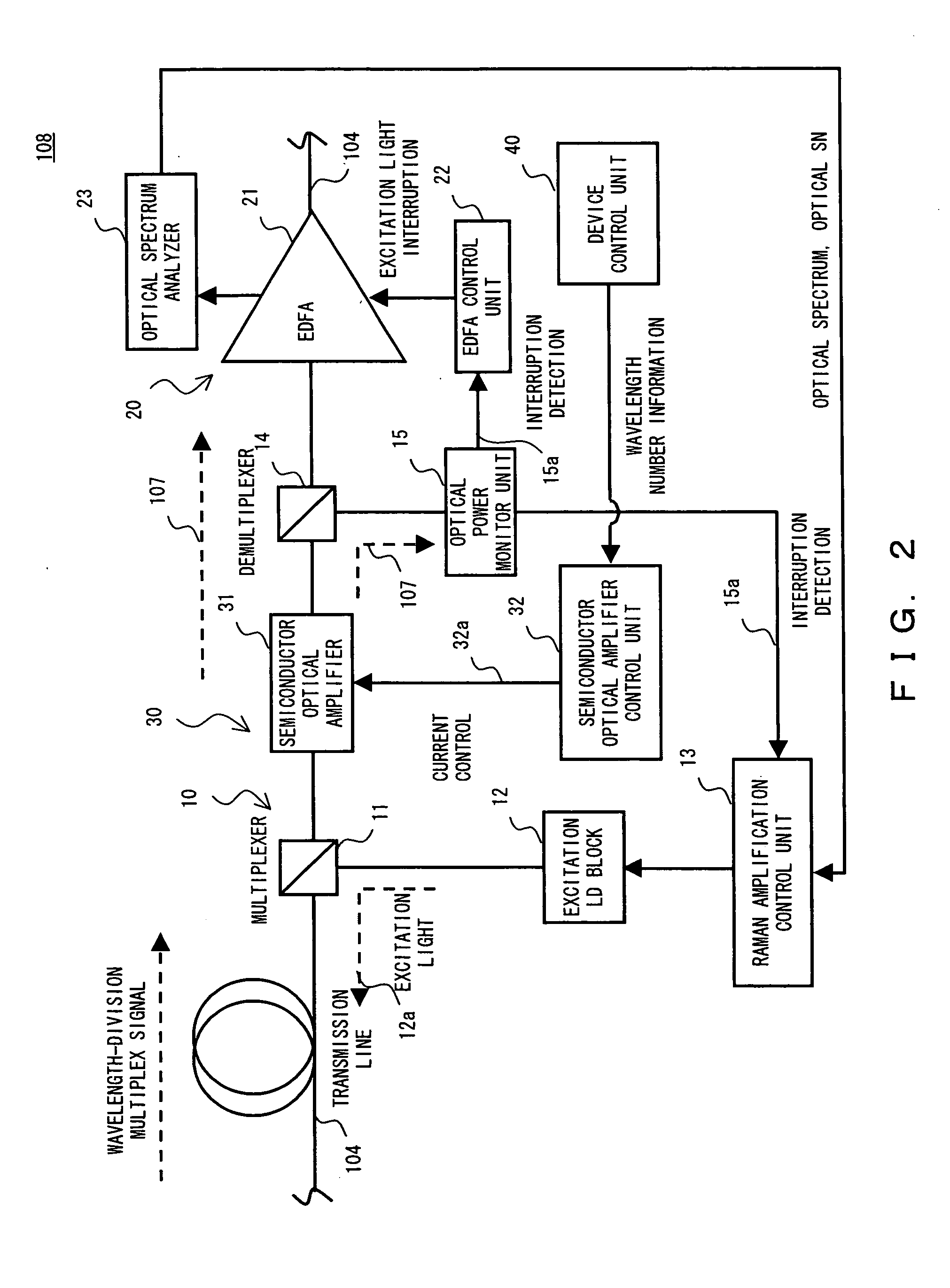
[0040]FIG. 2 shows one basic configuration of the optical amplification device in one preferred embodiment of the present invention. FIG. 3 shows one basic configuration of an optical wavelength-division multiplex transmission system including the optical amplification device in one preferred embodiment of the present invention.

[0041] As shown in FIG. 3, the optical wavelength-division multiplex transmission system 100 in this preferred embodiment comprises an electrical / optical converter 101 for converting an electrical signal containing transmission information into a plurality of optical signals 107a each with a different wavelength, an optical multiplexer 102 for multiplexing the plurality of optical signals 107a each with a different wavelength into wavelength-division multiplex signal light 107, an optical transmission line 104 composed of optical fibers for...


PUM


Abstract

The optical amplification device disposed in an optical transmission line for transmitting a plurality of segments of signal light each with a different wavelength comprises a first optical amplifier disposed in the optical transmission line, an optical power monitor unit provided in the down stream of the first optical amplifier in order to control the first optical amplifier, and a second optical amplifier, disposed between the first optical amplifier and the optical power monitor unit, capable of variably controlling the amplification band and absorption band of light.

Description

BACKGROUND OF THE INVENTION [0001] 1. Field of the Invention [0002] The present invention relates to an optical amplification device, a Raman amplifier, an optical wavelength-division multiplex transmission system and an optical wavelength-division multiplex transmission method, more particularly, to a technology effectively applied to an optical transmission technology for transmitting data for a long distance by applying wavelength-division multiplexing to signal light with a large number of wavelengths and the like. [0003] 2. Description of the Related Art [0004] In the recent optical communication technology, a wavelength-division multiplexing technology for transmitting data for a long distance by applying wavelength-division multiplexing to a plurality of segments of signal light each with a different wavelength is widely used. [0005] Conventionally, long-haul transmission has been realized by inputting excitation signal light with a wavelength approximately 100 m apart from a...

Claims


Application Information

Patent Timeline
IPC IPC(8): H01S3/00H01S3/067H01S3/10H01S3/30H04B10/07H04B10/079H04B10/2537H04B10/29H04B10/294H04J14/00H04J14/02
CPCH04B10/2931H04B10/2916
Inventor SHIMIZU, YOSHIHIRO
Owner FUJITSU LTD
Features
  • Generate Ideas
  • Intellectual Property
  • Life Sciences
  • Materials
  • Tech Scout
  • Unparalleled Data Quality
  • Higher Quality Content
  • 60% Fewer Hallucinations
Learn More