Metal injection molded suture needles

Inactive Publication Date: 2006-03-02
ETHICON INC
View PDF24 Cites 82 Cited by
  • Summary
  • Abstract
  • Description
  • Claims
  • Application Information

AI Technical Summary

Benefits of technology

[0008] An embodiment described herein is a method of making a suture needle having two or more cutting edges at a distal portion, comprising the steps of injecting a metal powder feedstock into a mold having at least one parting line, to obtain the suture needle wherein each cutting edges at the distal portion of the needle coincides with a parting line of the mold; and reducing the internal porosity of the suture needle to about 5 percent or less.

Problems solved by technology

However, in all of these examples, in order to accomplish attachment of a large diameter suture to suture needles produced from wire stock, additional, and often costly or time intensive processing steps are necessary.
Moreover, the stainless steel from which suture needles are commonly produced can be overworked in the process of forming the I-beam, resulting in embrittlement or even splitting of the wire from which the needle is made.
Furthermore, in many needle forming processes, the wire is often received in a hardened state making it exceptionally difficult to form into irregular shapes such as an I-beam.
If too little material is removed, flash and surface imperfections remain, but if too much material is removed, the cutting edges of the needle may be dulled.
While adding to the overall uniformity of the needle, the electropolishing process may detract from the performance of the needle.
However, MIM components are often considered to exhibit mechanical properties that are inferior to the properties that are attainable from components produced via machining operations.
Indeed the MIM process is often considered an inferior method for producing surgical devices when excellent mechanical performance is required.

Method used


Image

  • Metal injection molded suture needles
  • Metal injection molded suture needles
  • Metal injection molded suture needles

Examples


example 1

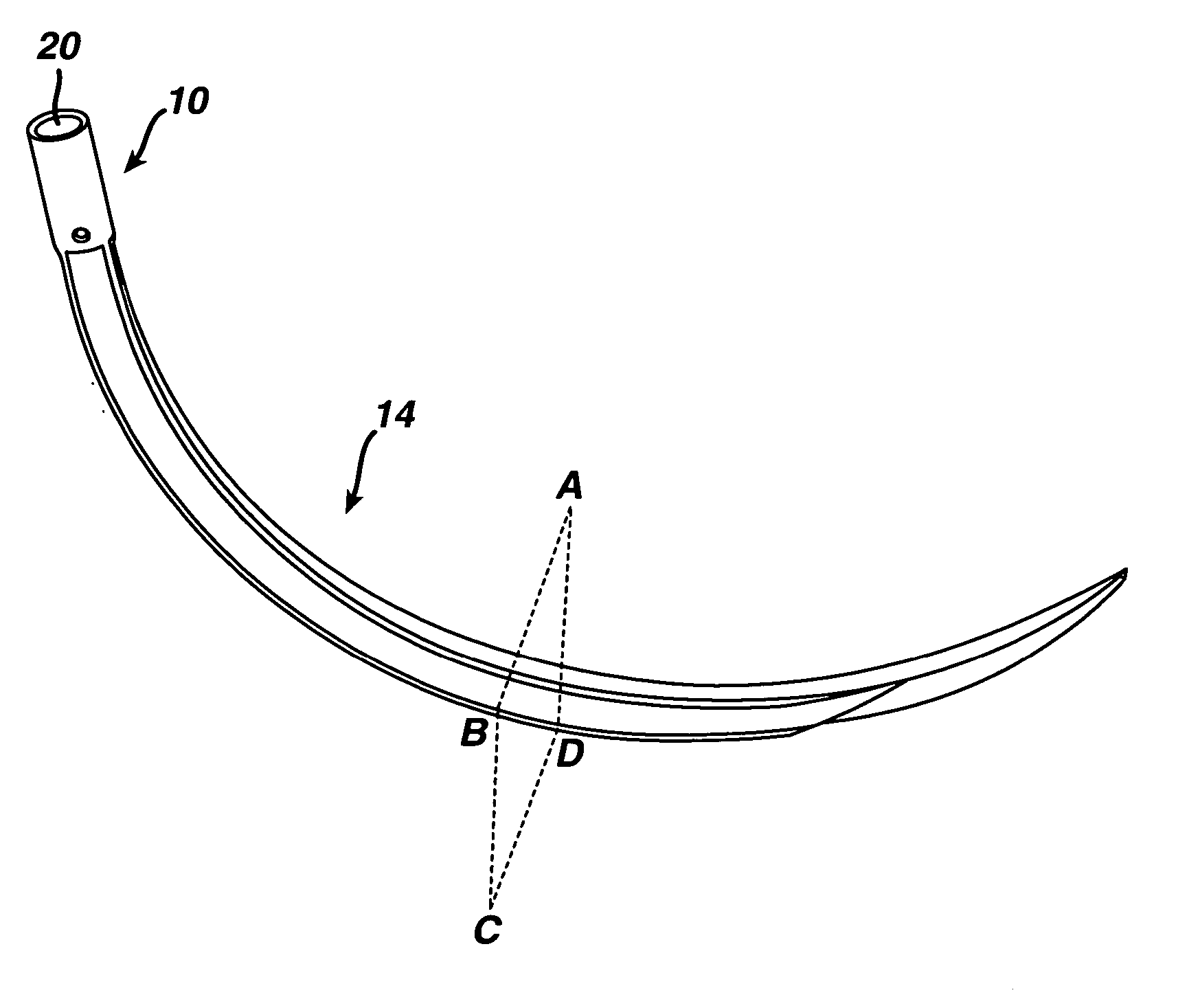
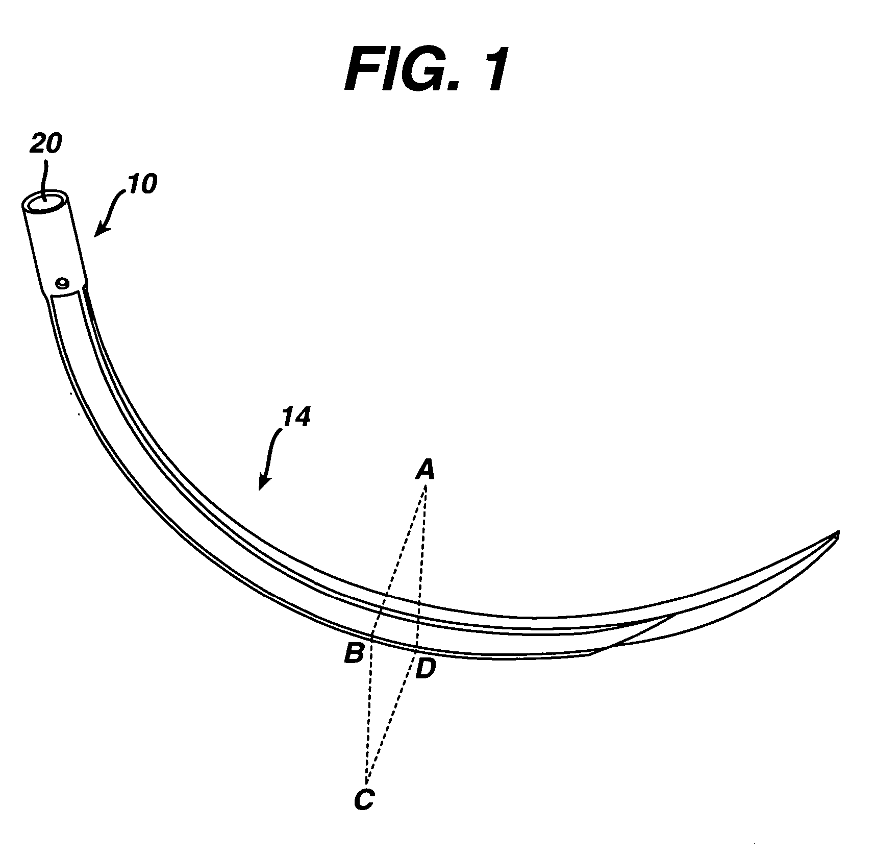
[0038] The needle that is schematically depicted in FIG. 1 was produced via metal injection molding. This needle has radiused or “undercut” cutting edge described by U.S. Pat. No. 5,797,961. The body portion is not round in cross-section but is rather rectangular with average dimensions of 0.0245″ by 0.0240″. In addition, as shown in FIG. 5, ribs have been molded into the inside and outside curvatures of the needle body. The proximal end of the needle shaft has an outside diameter of 0.030″ with an inside diameter of 0.024″ making it compatible with a size 2 suture according to United States Pharmacopia, USP, standards. The mold components used to produce this needle are shown in FIGS. 2, 3 and 6. Needles were molded from two different feedstock materials. The first feedstock contained the constituent powders of a martensitic stainless steel, commonly referred to as 420 grade. The other feedstock contained the constituent powders of a matensitic-aged, or mar-aged, stainless steel, c...

example 2

[0039] The suture needle schematically depicted in FIG. 7 was produced via MIM. This suture needle exhibits a standard cutting tip with three cutting edges 210 and flat faces 220 that taper to a point from the needle body, as shown in FIG. 9a. The needle body has ribs 240 as schematically depicted in FIG. 9b, which represents the cross-sectional view taken along E-F-G-H in FIG. 7. The height 250 and width 260 of the needle body were 0.0392″ and 0.0416″ respectively. The suture receiving hole 250 in FIG. 7, was 0.0060″ deep with an inside diameter of 0.0202″ and was able to accommodate a size 0 and 2-0 suture, referring USP standards. The four mold components used to form this needle, a core 255 and cavity 265, slide 275 and core pin 280, are shown in FIG. 10a in the open position. The mold components move from the open position schematically depicted in FIG. 10 a to closed position shown in FIG. 10b. A close-up view of the mold with the suture needle 285 included is shown in FIG. 11...

example 3

[0040] Suture needles produced from 420 stainless steel feedstock under the processing parameters described in Example 2 exhibited up to 6 volume percent internal porosity after the sintering process. A micrograph taken of the MIM needle described in Example 2 after the sintering process, but before a hot isostatic pressing process is shown in FIG. 12a. The black phase 300 is porosity and the light phase 310 is dense metal. The pores are evenly dispersed, ranging in size from a few micrometers to ˜50 micrometers. After subjecting the needles to a hot isostatic pressing process, wherein they were processed at 1100° C. for 3 hours under 104 MPa of gas pressure in an argon environment, the porosity was reduced to less than 1 volume percent. As shown in the optical micrograph of FIG. 12b, no dark phase is detectable indicating that the porosity was essentially eliminated. An improvement in ductility coincided with the decrease in internal porosity. As indicated by the dashed curve 350 i...


PUM

PropertyMeasurementUnit
Lengthaaaaaaaaaa
Fractionaaaaaaaaaa
Porosityaaaaaaaaaa

Abstract

The metal-injection molding (MIM) process offers distinct advantages over conventional wire-based methods for producing suture needles. Methods for producing unique suture receiving holes that accommodate large diameter sutures and facilitate adhesive attachment of said sutures are described herein. Additionally, methods for producing cutting edge suture needles that exhibit exemplary tissue penetration performance are described. Finally, the ductility of suture needles produced via the MIM process have been enhanced substantially by employing processes that reduce the internal porosity of the suture needle component.

Description

FIELD OF INVENTION [0001] The invention pertains to suture needles commonly used to guide and place sutures about a surgical wound. More specifically, the invention pertains to suture needles produced via the metal injection molding process. Novel design features facilitated by the metal injection molding process and methods for improving suture needle properties are disclosed. BACKGROUND OF INVENTION [0002] Several researchers have recognized the benefits associated with the ability to attach large diameter sutures to smaller diameter suture needles. The potential benefits include: less tissue trauma from the smaller suture needles, less force required to pass smaller needles through tissue, and enhanced hemostasis at the hole formed in the tissue by virtue of the larger suture plugging the smaller hole left behind by the needle. Matsutani et al. describe a method in U.S. Pat. No. 4,501,312 wherein the proximal end of a suture needle produced from wire is hot forged with a mandrel ...

Claims


Application Information

Patent Timeline
IPC IPC(8): A61B17/06
CPCA61B17/06066A61B2017/06028A61B2017/0608B21G1/00B22F3/225B22F5/10B22F2998/00B22F2998/10B22F3/22B22F3/15
Inventor CICHOCKI, FRANK R. JR.
Owner ETHICON INC
Why Eureka
Try Eureka