Power controller for fuel cell

a fuel cell and power controller technology, applied in the field of electrochemical power systems, can solve the problems of large output voltage swing, which occurs, and difficulty in coupling the direct output of the fuel cell to electrical loads, and achieve the effect of reducing the variance of cell performan

Inactive Publication Date: 2006-03-09
GENESIS FUEL TECH INC
View PDF7 Cites 20 Cited by
  • Summary
  • Abstract
  • Description
  • Claims
  • Application Information

AI Technical Summary

Benefits of technology

[0007] The present invention provides simplified means of protecting the cells in a fuel cell from damage, utilizing a novel circuit combined with a DC-DC converter.
[0008] In a properly operating fuel cell system, variances in the cell-to-cell voltages will be small. These differences, however, are most pronounced at maximum current levels where the cell voltages are at their minimum points. Furthermore, it is important to maintain a minimum cell voltage, particularly at higher amperage conditions. This is because the waste heat generated within the cell increases as the cell voltage drops. For example, in a hydrogen / air fuel cell system, the waste heat per cell will equal: Waste heat=(1.254−Cell Voltage) *Cell Current   (1) where the open circuit potential is 1.254 volts. As the cell voltage drops below zero volts, all of the wattage in the cell will typically be dissipated as heat. To prevent excess heat from being generated in a cell, each cell is ideally kept above approximately 0.5 volts in hydrogen / air fuel cell systems. For this reason, each cell is usually monitored. This can prevent physical damage of the cell caused by excessive temperature when a cell becomes negatively biased.
[0009] Another method of preventing cell overheating is to limit the current during a reverse-biased cell event. For example, from equation (1), if a cell is operating at 0.627 volts and 10 amperes, the waste heat will equal 6.27 watts. This waste heat in a typical fuel cell system will be dissipated by a cooling means, which maintains the fuel cell at a desired temperature. In the case where the cell becomes negatively biased at −0.627 volts, the current must be decreased by lowering the amperage to 3.33 amperes in order to keep the cell at the same temperature. This lower amperage will mean that the remaining cells will have a voltage higher than 0.627 volts / cell, assuming they are operating properly. Therefore, there can be a group of cells, where if a minimum voltage is maintained for that group of cells, a reverse-biased cell may actually cool down instead of overheat. If we assume that the cells produce 3.33 amperes at 0.766 volts / cell, for example, a group of 10 cells held at a minimum of 6.27 volts will compensate for a single reverse-biased cell of −0.627 volts by lowering the current, such that the power dissipation for the reverse-biased cell will be the same as when the cell was operating normally at +0.627 volts. Selection of the minimum number of cells and the minimum composite voltage can thus guarantee thermal stability of the cells, preventing the so-called “thermal runaway” situation seen in certain fuel cell types.
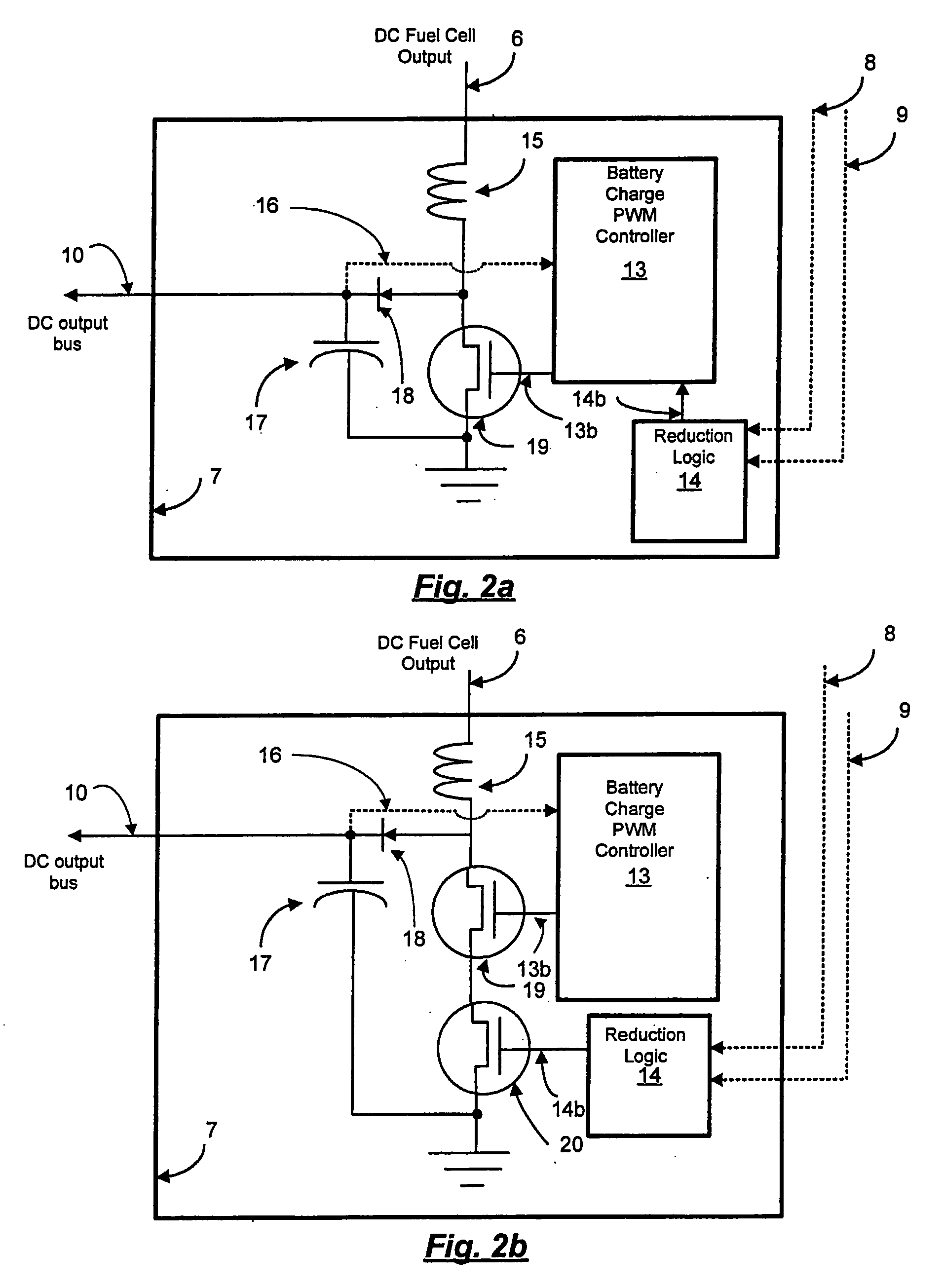
[0010] Reducing the physical interval of data-taking to several groups of cells in a fuel cell stack decreases cost. However, it is possible to decrease cost further by eliminating the need to carefully monitor the fuel cell voltage itself with a microprocessor. For example, in a DC-DC converter power system coupled to a fuel cell stack, it not important for the converter to-know the exact voltages of the cells, or even groups of cells. All that is needed is for the voltage of each group of cells to exceed a set minimum voltage. A comparator and a reference voltage provide a means for accomplishing this for each group of cells, and the Boolean combination of these comparisons provide a means for limiting the power draw from the fuel cell with the DC-DC converter when necessary, thus protecting the fuel cells from overheating.
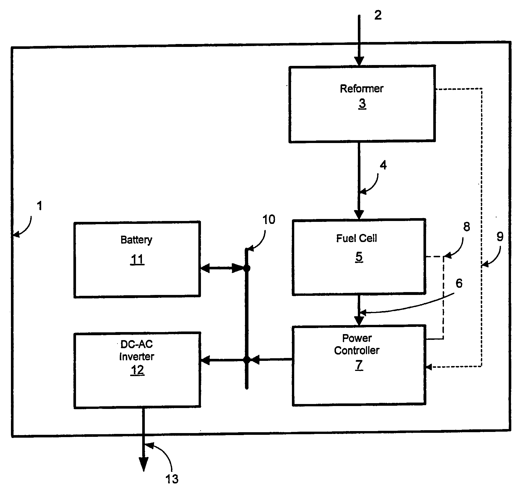
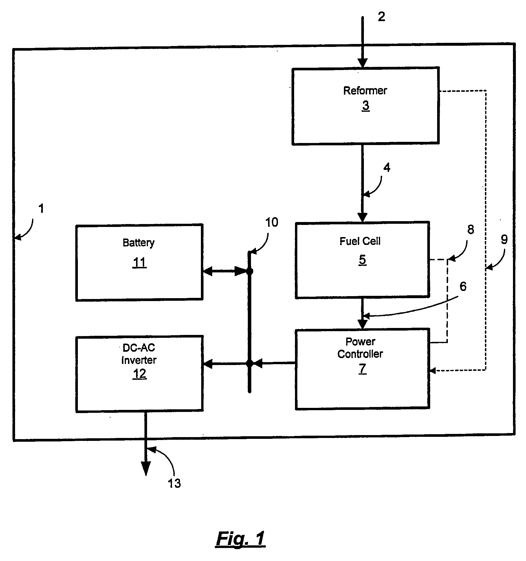
[0012] Reduction of the fuel cell current to maintain a desired voltage of a fuel cell group can protect individual cells from overheating. An additional protective measure is also useful when the hydrogen is supplied from a reformer or other hydrogen producing device. In this case, variations in load may cause temporary shortfalls in the supply of hydrogen, causing the hydrogen supply pressure to the fuel cell to drop too low for effective operation of the fuel cell. When this occurs the current in the fuel cell may be reduced through the control of the DC-DC converter such that the hydrogen supply pressure to the fuel cell is always maintained above a certain pressure. In such cases it is typically advantageous to have a battery to supply power to the load when the fuel cell output is temporarily limited to maintain a minimum hydrogen feed pressure.

Problems solved by technology

One of the drawbacks with fuel cells is the wide swing in the output voltage, which occurs as the load varies.
This makes coupling the direct output of the fuel cell to electrical loads difficult.
In the course of operating a fuel cell, there will typically be some variance in performance between the cells of a multi-cell system.
In severe instances, a single cell can become negatively biased at higher current levels, so that all of the current and voltage in the cell produces heat.
This can, in turn, destroy the individual cell.
Sensing each cell voltage in a multi-cell fuel cell system adds cost and complexity.
Since each cell is at a different potential, this circuit can become quite complex, adding cost to the fuel cell system.

Method used


Image

  • Power controller for fuel cell
  • Power controller for fuel cell
  • Power controller for fuel cell

Examples


Embodiment Construction

[0019]FIG. 1 schematically illustrates a typical embodiment of a fuel cell power system with a power controller. Enclosure 1 contains reformer 3, which draws fuel through fuel inlet 2. Hydrogen produced by reformer 3 travels to fuel cell 5 via hydrogen line 4. Electrical power produced by fuel cell 5 is sent via line 6 to power controller 7, where it is then routed to DC bus 10. DC bus 10 can charge batteries 11 or send power to DC-AC inverter 12. Power controller 7 is configured to reduce the power output of fuel cell 5 responsive to one or both of the signals in lines 8 and 9. Line 8 provides a signal representative of the voltage across a stack or plurality of fuel cells while line 9 provides a signal representative of hydrogen pressure to fuel cell 5 in line 4. Reformer 3, fuel cell 5, battery 11 and DC-AC inverter 12 may be of any conventional type, and their structure and operation are well known to those skilled in this art.

[0020]FIGS. 2a and 2b depict a representative power...


PUM

PropertyMeasurementUnit
pressureaaaaaaaaaa
voltageaaaaaaaaaa
voltageaaaaaaaaaa

Abstract

A fuel cell power system includes a fuel cell stack having at least two fuel cell groups in series with each other and with each fuel cell group having more than one individual fuel cell, and a power controller which receives electrical power from the fuel cell stack and distributes the electrical power to an output bus. The power controller includes a DC-DC converter, and a reduction logic circuit operative to limit current through the DC-DC converter in response to voltage across each fuel cell group so that a minimum voltage is maintained across each fuel cell group. When used in combination with a hydrogen reformer, the reduction logic circuit is also operative to limit current through the DC-DC converter in response to hydrogen pressure supplied by the reformer to the fuel cell stack so that a minimum pressure is maintained for the hydrogen supplied to the fuel cell stack.

Description

FIELD OF THE INVENTION [0001] This invention relates to electrochemical power systems which utilize a power controller for regulating the power output of electrochemical fuel cells. Specifically, a power controller is disclosed which has means to protect a fuel cell from undervoltage conditions which may cause damage to the cells. In the preferred embodiment, this controller includes a DC-DC converter which also provides a regulated power output suitable for charging batteries or powering loads. BACKGROUND OF THE INVENTION [0002] Fuel cell power systems are becoming an increasingly viable source of electrical power for a wide variety of applications. Potential uses vary from miniature power systems for hand-held scanners to electromotive power for oceangoing vessels. [0003] One of the drawbacks with fuel cells is the wide swing in the output voltage, which occurs as the load varies. This makes coupling the direct output of the fuel cell to electrical loads difficult. To mitigate thi...

Claims


Application Information

Patent Timeline
Patent Type & Authority Applications(United States)
IPC IPC(8): H01M8/04H01M8/06
CPCH01M8/04552H01M8/04559Y02E60/50H01M8/249H01M16/006H01M8/0491Y02E60/10
Inventor DEVRIES, PETER DAVID
Owner GENESIS FUEL TECH INC
Why Eureka
Try Eureka