Plasma display filter with a dielectric/metallic layer stack of at least eleven layers

a technology of dielectric/metallic layer stack and filter, applied in the field of optical filters, can solve the problems of conflicting design factors regarding the design of pdp filters, color change distracting, and difficulty in maintaining target levels

Inactive Publication Date: 2006-03-16
SOUTHWALL TECH INC
View PDF4 Cites 42 Cited by
  • Summary
  • Abstract
  • Description
  • Claims
  • Application Information

AI Technical Summary

Benefits of technology

[0018] An advantage of the invention is that the plasma display filter exhibits desirable characteristics with regard to a number of different concerns, including infrared and EMI shielding, color transmissivity, and reflected color shift with angle. Thus, for example, the infrared light transmittance at 950 nm may be less than one percent.

Problems solved by technology

Unfortunately, modifying a filter to increase conditions with respect to one factor sometimes conflicts with maintaining a target level for another factor.
Any color change is distracting when a display is viewed from a close distance, where the color of the display appears to change across the surface.
In particular, it is objectionable if the “red-green” component of color, Ra*, changes substantially with angle.
As previously noted, different factors regarding the design of PDP filters may conflict.
Infrared radiation is relatively close in wavelength to red and is therefore difficult to effectively control while simultaneously obtaining low reflection in the red region of the spectrum (i.e., 620-700 nm).
Controlling reflection within the red region of the light spectrum is rendered even more difficult by the need for a low sheet resistance in the PDP filter 12.
The requirement for lower sheet resistance increases the color problem for etalon EMI filters.
The transmission bandwidth of the filter becomes narrower as the conductive layers become thicker, resulting in both an increase in the red reflection and a loss of color bandwidth in transmission.
There is a conflict between the tendency of etalon filters to show red reflection at different viewing angles and the generally expected appearance of consumer products.
This objectionable reflection limits the thickness of the conductive layers used in such filters.
In addition, there is a large color shift with incidence angle, which creates an apparent color difference across the screen for a large screen viewed at a close distance.
Thus, despite the suitability of the coating for some Class B EMI applications, this coating may be considered cosmetically unacceptable.

Method used


Image

  • Plasma display filter with a dielectric/metallic layer stack of at least eleven layers
  • Plasma display filter with a dielectric/metallic layer stack of at least eleven layers
  • Plasma display filter with a dielectric/metallic layer stack of at least eleven layers

Examples


example 1

[0030] The structure of FIG. 3 may be fabricated using indium oxide as the dielectric material and silver as the metallic material. A thin titanium layer (less than 2 nm thickness) may be deposited on top of each silver layer prior to deposition of the dielectric material, so as to improve the silver conductivity. Table B shows the materials and thicknesses for nineteen layers of one sample formed in accordance with the invention. The alternating pattern 26 of FIG. 3 is comprised of Layers 4 through 14. This alternating pattern is formed on a first PET substrate (Layer 3) that is joined to a thicker substrate (Layer 1) by a layer of pressure sensitive adhesive. Additionally, a color-correcting AR coating (i.e., an AR coating exhibiting a negative Ra* shift with increasing angle of incidence) is achieved by the combination of Layers 17, 18 and 19. The color correction is a result of a proper selection of materials having particular indices of refraction. In the embodiment of Table B,...

example 2

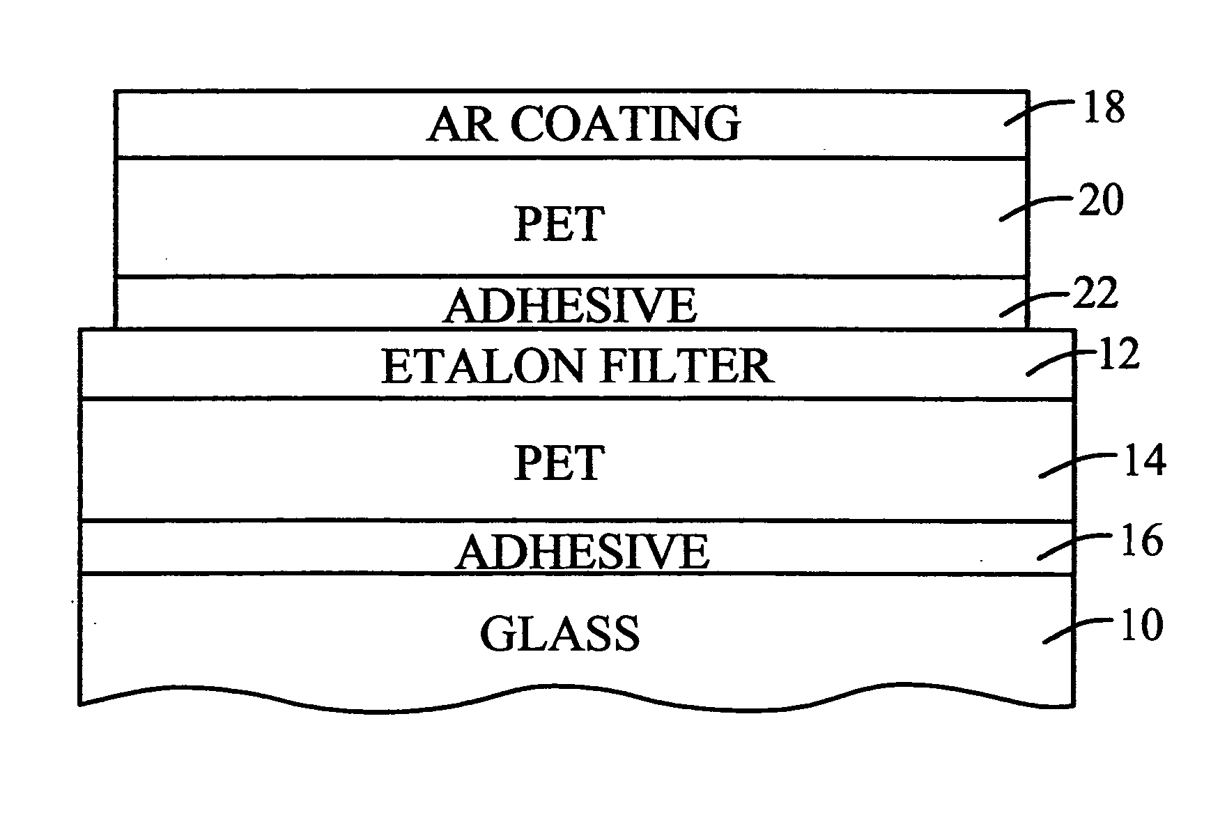
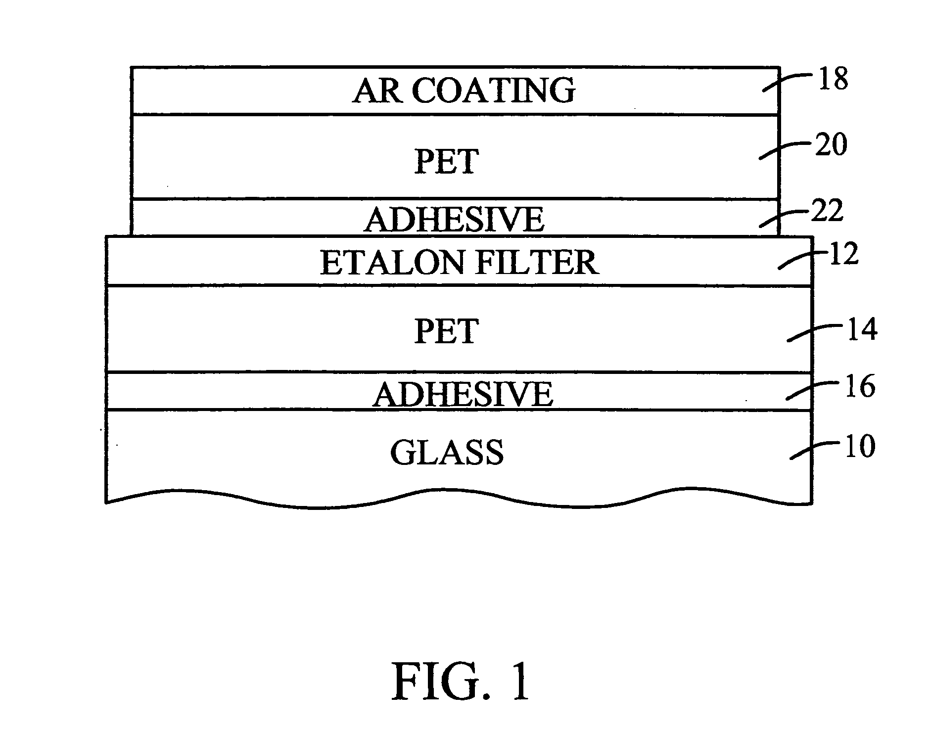
[0032] A sample of the structure formed in accordance with FIG. 3 was laminated as in FIG. 1, with a commercial antireflective coating 18. The structure was then annealed for 48 hours at 100° Celsius in air. The annealing did not change the optical properties in transmission or in reflection. However, the sheet resistance was reduced from 0.96 ohms / square to 0.80 ohms / square.

example 3

[0033] In another sample, the coating as described in Example 1 was over-coated with an acrylic antiglare hardcoat, such as the hardcoat 58 in FIG. 3. The structure was then laminated to a glass sheet. The resulting sample exhibited excellent transmission and reflection characteristics. The sheet resistance was 1.0 ohms / square.


PUM

PropertyMeasurementUnit
thicknessesaaaaaaaaaa
angle of incidenceaaaaaaaaaa

Abstract

A plasma display filter includes five metallic layers, such as silver alloy layers, having a combined thickness that exceeds 50 nm. The metallic layers form an alternating pattern with dielectric layers, where the layer in the pattern closest to a supporting substrate is the first of the dielectric layers. Layer thicknesses are selected to achieve a low reflected color shift with changes in the viewing angle, relatively neutral transmitted color properties, and desirable shielding characteristics with respect to infrared and electromagnetic radiation.

Description

TECHNICAL FIELD [0001] The invention relates generally to optical filters and more particularly to filters for plasma display panels. BACKGROUND ART [0002] A number of different factors are considered in the design of an optical filter for a plasma display panel (PDP). The factors include the degree of neutrality of transmitted color, the level of reflected light and the color shift with changes in the incidence angle of a viewer, and the transmission levels of infrared and electromagnetic radiation. Unfortunately, modifying a filter to increase conditions with respect to one factor sometimes conflicts with maintaining a target level for another factor. [0003]FIG. 1 is one possible arrangement of layers to provide a filter for a plasma display panel, which includes a module or separate glass sheet 10. The Etalon filter 12 is first formed on a polyethylene terephthalate (PET) substrate 14 that is then affixed to the glass sheet by a layer of adhesive 16. Because a plasma display gene...

Claims


Application Information

Patent Timeline
Patent Type & Authority Applications(United States)
IPC IPC(8): H01J1/62H01J63/04H01J17/49
CPCG02B5/284G02B5/285H05K9/0096H01J11/44H01J11/10
Inventor LAIRSON, BRUCE M.LOUIE, STANLEYSCHMIDT, CHRIS R.GADERLUND, ERIK
Owner SOUTHWALL TECH INC
Why Eureka
Try Eureka