Steam generation apparatus and method

a technology of steam generation apparatus and steam, which is applied in the direction of steam boilers, preheating, water circulation, etc., can solve the problems of escalating costs, significant cost to the producer, and uneconomical projects, and achieve the effect of increasing the steam quality of the steam passing

Inactive Publication Date: 2006-03-30
ACS ENG TECH
View PDF6 Cites 18 Cited by
  • Summary
  • Abstract
  • Description
  • Claims
  • Application Information

AI Technical Summary

Benefits of technology

[0014] The liquid fuel can include, for example, bitumen or heavy oil. Of course other fuels such as medium oil, light oil, etc. could be used. However, the lower grade fuels may be relatively more economical and more readily available (i.e. on site at an in situ operation where steam generation is required).
[0021] The liquid fuel can be taken from in situ production. It may be advantageous to use the liquid fuel while it retains latent heat from production so that it has a viscosity that facilitates handling.
[0023] In accordance with another broad aspect, there is provided a steam generation apparatus comprising: a steam injection boiler including a burner operable therein and a boiler water coil extending through the steam injection boiler and including an outlet the boiler water coil selected to convey water in order to heat the water to generate steam; at least a first heater and a second heater, each including a steam heating circuit, the steam heating circuits being connected in parallel with each other and in fluid flow communication with the boiler water coil and the heater selected to increase the steam quality of the steam passing from the steam injection boiler; and a flow controller to control flow through the first and the second heaters and actuable to select that flow is permitted through only a selected one of the first heater steam heating circuit and the second heater steam heating circuit.
[0025] In accordance with yet another broad aspect of the present invention, there is provided a method for generating steam comprising: providing a steam injection boiler including a burner operable therein and a boiler water coil extending through the steam injection boiler and including an outlet the boiler water coil selected to convey water in order to heat the water to generate steam; at least a first heaters and a second heater, each including a steam heating circuit, the steam heating circuits being connected in parallel with each other and in fluid flow communication with the boiler water coil and selected to increase the steam quality of the steam passing from the steam injection boiler; and a flow controller to control flow through the first and the second heaters and actuable to select that flow is permitted through only a selected one of the first heater steam heating circuit and the second heater steam heating circuit; conveying water through the boiler water coil and through the steam heating circuit of a selected one of the first heater or the second heater to generate steam from the water; defouling the steam heating circuit of the other of the first heater or the second heater; and switching flow to the other of the first heater or the second heater when the steam heating circuit of the selected heater when it is desired to defoul the selected steam heating circuit.

Problems solved by technology

Producing very high quality steam of greater than 80% quality typically results in escalating cost due to water treatment costs, potentially rendering a project uneconomical.
Conversely, lower than 80% quality steam introduces inefficiencies to the process utilized for heavy oil or bitumen recovery and, hence, is also undesirable from a cost perspective.
Unfortunately, however, the gaseous fuel must often be piped significant distances to the location of steam generation, resulting in a significant cost to the producer due to the price of the gaseous fuel and the cost of the associated pipeline construction and maintenance.
However, conversion of SIB units from gas fuel to liquid fuel, such as heavy oil or bitumen, has been problematic for a number of reasons.
For example, since the flame resulting from firing natural gas is generally shorter than the flame resulting from firing liquid fuel, such as bitumen or heavy oil, the conversion of an existing SIB unit from gas firing to liquid fuel firing inevitably leads to lower firing rates as the combustion chamber of an existing SIB unit is only designed and sized to accommodate operating conditions incidental to gas firing.
While lower firing rates of bitumen can be used and adjusted to mimic the gaseous fuel flame envelope size restrictions of the existing combustion chamber, these lower firing rates result in lower steam generating capacity, as well as lower quality steam (i.e. less than 80% quality).
Combusting bitumen or heavy oil also requires the utilization of emission reduction / abatement technologies and equipment, as these liquids generally contain sulfur and other metallic components, resulting in undesirable by-products when combusted.
Even in new installations, the problems associated with liquid fuel firing has driven the industry to continue to use gaseous fuels.
This results in extra costs for equipment, transport and installation.

Method used


Image

  • Steam generation apparatus and method
  • Steam generation apparatus and method
  • Steam generation apparatus and method

Examples


Embodiment Construction

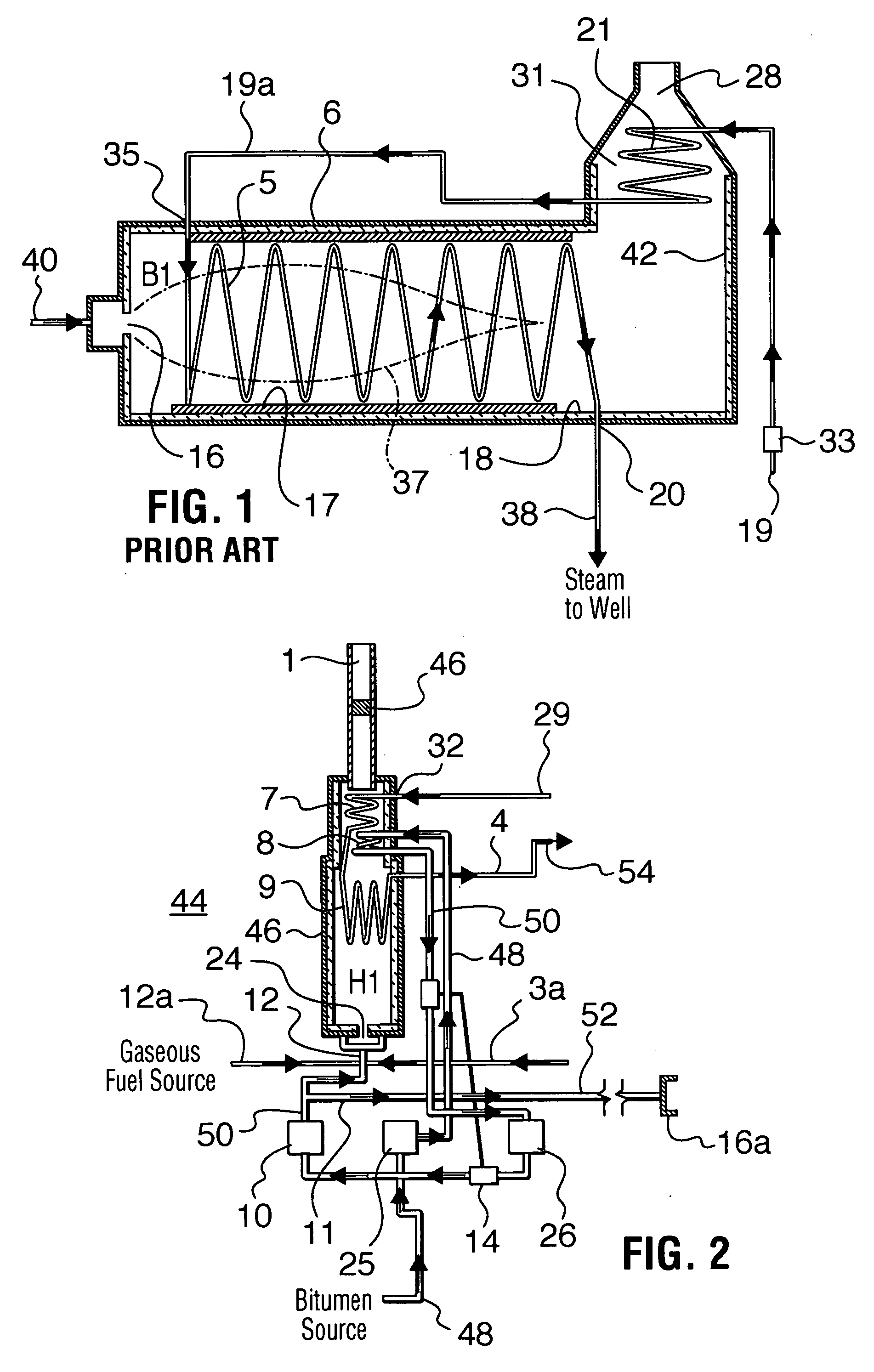
[0034] Referring to FIG. 1, a prior art steam injection boiler B1 is shown. Similar steam injection boilers are alternately termed “steam flood boilers”, “water flood boilers” or “once through steam generators”. Some of the leading manufacturers include Struthers Industries Inc., Gulfport, Miss., HTH Heatech Inc., Calgary, Alberta and Applied Thermal Systems (ATS) Inc., Tulsa, Okla.

[0035] The steam injection boiler includes a combustion chamber defined by an outer wall 6. Combustion chamber includes a burner 16 for handling gaseous fuel such as liquid petroleum gas or natural gas supplied through line 40. Burner 16, when in operation, creates, a flame shown in phantom as 37, and combustion chamber thereby includes a radiant zone, a convection zone 31 and an exhaust stack 28. The outer wall has a refractory lining 18.

[0036] A feed water line 19 feeds water by use of a feed pump 33 to coils in the boiler for the generation of steam from the water. In particular, feed water line 19 l...


PUM


Abstract

In one aspect, the invention provides a steam generation apparatus that is liquid fuel fired and addresses conversion of gaseous fuel SIB units to operate with liquid fuel. The invention also relates to a conversion unit for a steam injection boiler, a method for converting a steam injection boiler from gas firing to possible liquid fuel firing and a method for generating steam from a liquid fuel source. The invention employs a fired heater for heating the liquid fuel to a temperature suitable for firing and preheats the water to compensate for the shortfall in beat liberation when a gas boiler is converted to use liquid fuel. In another aspect of the invention, production of steam is achievable consistently by employing step-up heaters with a steam injection boiler. The heaters being connected in parallel to continue heating the water / steam to achieve a higher quality steam over that produced in the boiler while minimizing consideration as to the adverse effects of coil fouling in the boiler.

Description

BACKGROUND OF INVENTION [0001] The present invention relates to steam generation apparatus and, in particular, steam generation apparatus for secondary recovery of oil, a conversion unit for steam generation apparatus and methods for steam generation and conversion of steam generation apparatus. [0002] Steam is often used in industrial processes. For example, steam can be used for heat exchange, as a power source for driving turbines, etc. [0003] In the petroleum industry, for example, steam can be used for extraction processes and to enhance production. In one procedure, steam may be used for the recovery of bitumen or heavy oil from oil-bearing formations. A common process utilized for the in situ recovery of heavy oil or bitumen is to inject steam underground pursuant to which the viscosity of bitumen or heavy oil is decreased such that it flows and is capable of being pumped to the surface. For this, steam generation equipment commonly called steam injection boilers (“SIB”) are ...

Claims


Application Information

Patent Timeline
Patent Type & Authority Applications(United States)
IPC IPC(8): F22D7/00F22B31/00
CPCF22B31/00
Inventor SARKAR, SUJIT K.
Owner ACS ENG TECH
Why Eureka
Try Eureka