Method of recovering blood from an extracorporeal circuit

Inactive Publication Date: 2006-03-30
SAMOLYK KEITH A
View PDF23 Cites 8 Cited by
  • Summary
  • Abstract
  • Description
  • Claims
  • Application Information

AI Technical Summary

Benefits of technology

[0020] Once the concentration reaches a satisfactory level, the outlet port of the hemo-bag is clamped off and, preferably, the blood in the post-operative recovery or recirculation circuit is chased into the bag as the pump operates, by allowing clear crystalloid fluid or air through, for example, a Luer port near the closed outlet port of the bag. Once crystalloid fluid or air enters the hemo-bag, the pump is stopped, the bag inlet port is then clamped off, the hemo-concentrator is disconnected, and the caps on the bottom are reclosed. T

Problems solved by technology

Although some such diluted blood can be transfused to the patient, a relatively large fraction of the volume of the CPB circuit cannot be transfused, because this volume is needed to maintain the integrity of the circuit in the event full bypass is to be resumed.
This option also suffers from the dilution of important blood components and the need to keep a large fraction of the diluted blood in the circuit to maintain circuit integrity.
This is common in pediatric open heart cases, but benefits neither the patient nor anyone else, and presents a significant disposal problem to the perfusionist (i.e., the operator of the heart/lung machine), who must clean up and discard this wasted volume.
Because in the foregoing options, the patient cannot re

Method used


Image

  • Method of recovering blood from an extracorporeal circuit
  • Method of recovering blood from an extracorporeal circuit
  • Method of recovering blood from an extracorporeal circuit

Examples


Embodiment Construction

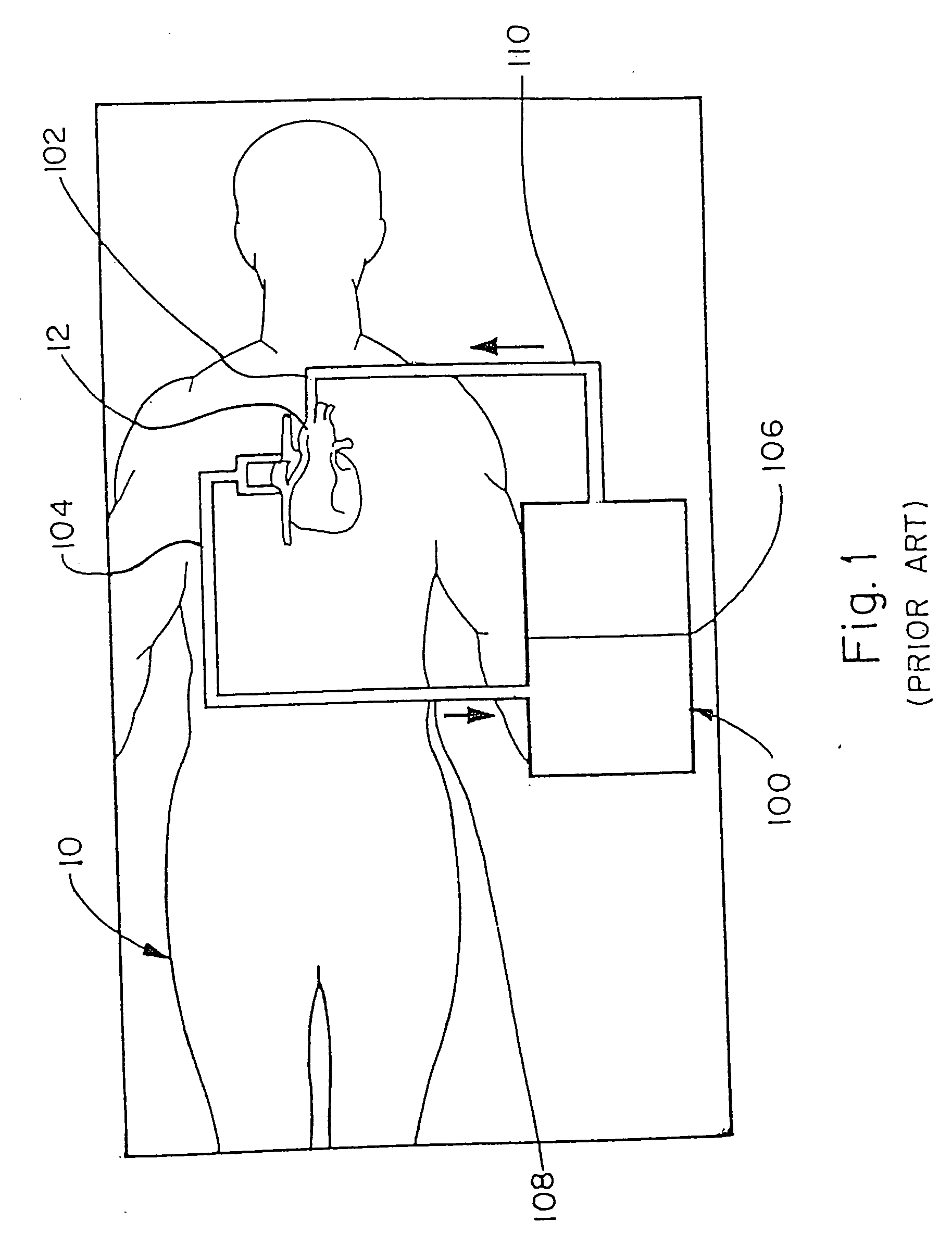
[0030]FIG. 1 schematically shows a patient 10 during heart bypass surgery, wherein a cardiopulmonary bypass (CPB) system, also known as a heart / lung machine 100, is connected to the patient's heart 12. The CPB system 100 includes an arterial cannula 102 inserted into the aorta at the heart 12 and a venous cannula 104 inserted into one or both of the vena cava. Arterial pump 106 (and associated components to be described hereinafter), receives deoxygenated blood from the venous cannula 104, via inlet line 108, and delivers externally oxygenated blood via outline line 110, to the arterial cannula 102.

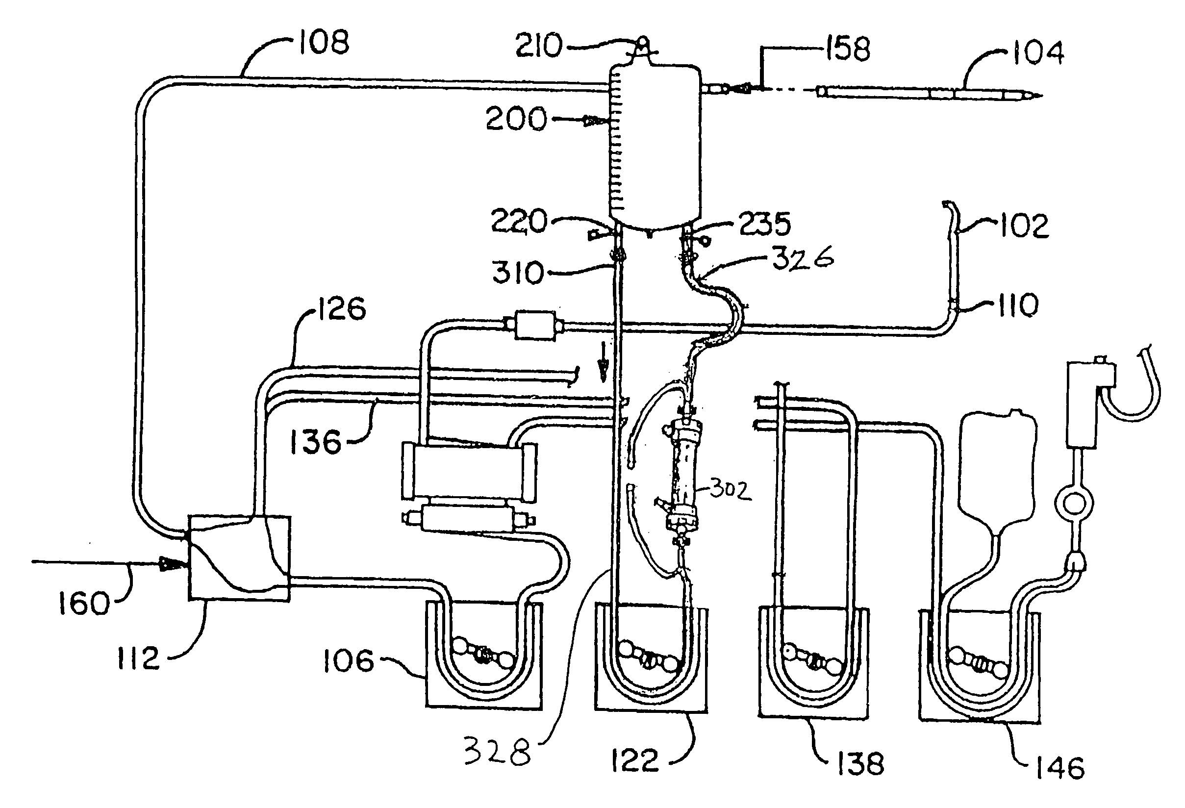
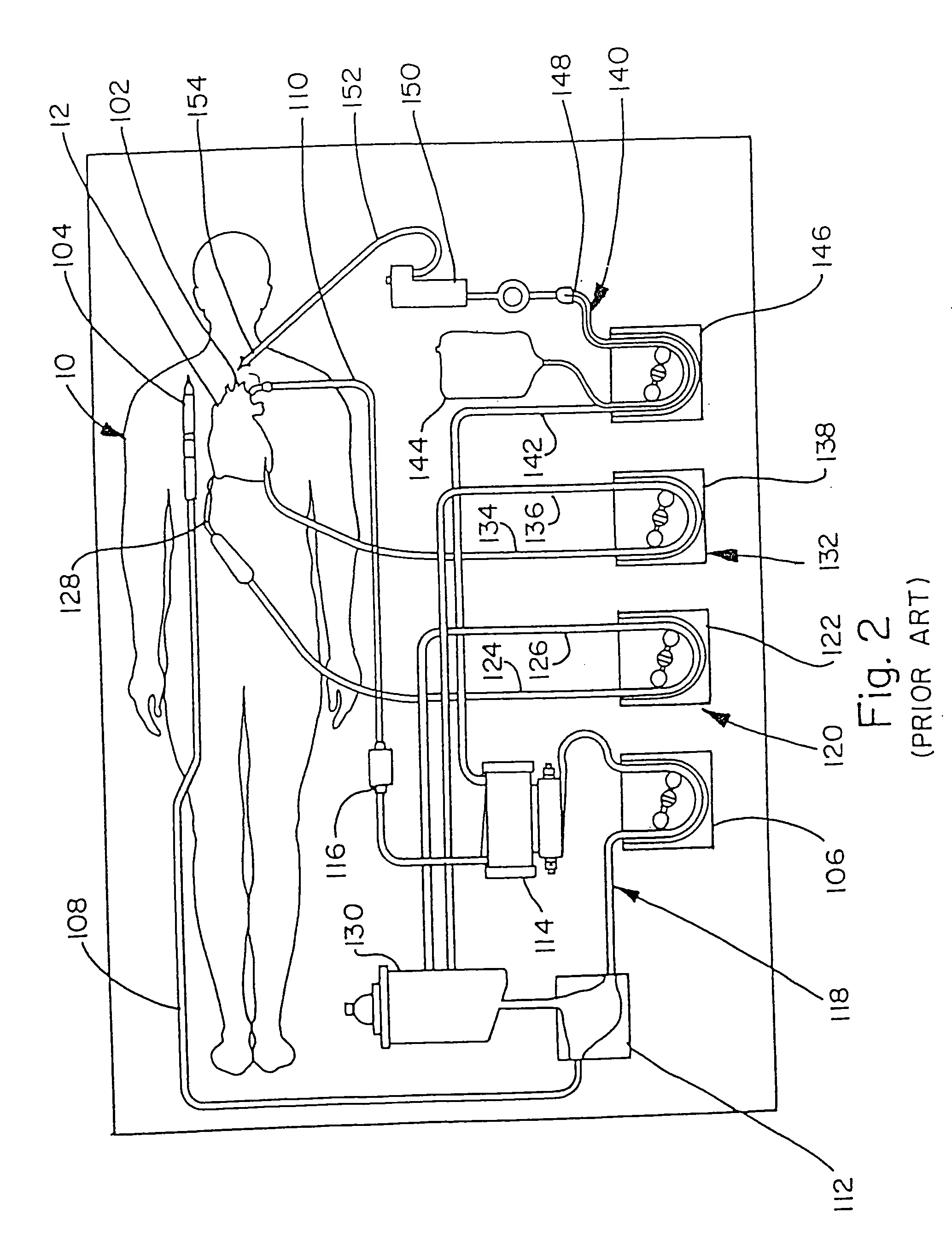
[0031]FIG. 2 shows additional details represented schematically, of one conventional arrangement by which the CPB system 100 is connected to the patient 10 during bypass surgery. Deoxygenated blood in the inlet line 108 enters a venous reservoir 112, which is fluidly connected to the arterial pump 106. The discharge from the pump 106 enters a heat exchanger and oxygenator 114, passes thr...


PUM


Abstract

The invention is directed to a blood bag system, comprising a closed, sterile bag of substantially transparent, bio-compatible material, defining upper and lower ends; an infusion port at the upper end of the bag; an outlet port at the lower end of the bag; an inlet port at the lower end of the bag; a hemo-concentrator having an inlet port and an outlet port; a pair of inlet tubes fluidly connected to the hemo-concentrator inlet port; and a pair of outlet tubes fluidly connected to the hemo-concentrator outlet port. One of the inlet tubes is fluidly connected to the outlet port of the bag, and one of the outlet tubes fluidly connected to the inlet port of the bag. The other of the inlet tubes and the other of the outlet tubes are temporarily sealed (e.g., clamped) to prevent flow therethrough. The bag, the one outlet tube, the hemo-concentrator, and the one inlet tube thus form a closed fluid circulation circuit by which a pump can recycle the blood through the hemo-concentrator. One aspect of the invention includes a hemo-concentrator system and a specially adapted tubing set, for easily and quickly converting the hemo-concentrator from conventional use to use in the blood recovery method. Other aspects of the invention are directed to the combination of tubing set with hemo-concentrator, and to the tubing set itself.

Description

RELATED APPLICATIONS [0001] This application is a divisional of U.S. patent application Ser. No. 10 / 159,553 filed May 31, 2002, which is a continuation-in-part of U.S. application Ser. No. 09 / 189,230 filed Nov. 11, 1998, issued on Jun. 4, 2002, as U.S. Pat. No. 6,398,751, which is a divisional of U.S. application Ser. No. 08 / 719,971 filed Sep. 24, 1996, now U.S. Pat. No. 5,928,178.BACKGROUND OF THE INVENTION [0002] The present invention relates to medical equipment, techniques and procedures, and more particularly, to the circulation and recovery of blood during and immediately following heart bypass surgery. [0003] A persistent dilemma is faced thousands of times each day worldwide, of how to handle the volume of a patient's blood in the circuit of a cardiac pulmonary bypass system (heart-lung machine), after the surgical procedure has been completed and the patient is disconnected from the bypass system. [0004] One option is to transfuse the volume in the cardiopulmonary bypass (C...

Claims


Application Information

Patent Timeline
IPC IPC(8): A61M1/34A61M37/00A61J1/00A61J1/05A61M1/36
CPCA61J1/10A61M1/0281A61M1/34A61M1/3646A61M2230/207Y10S128/24A61M1/3603A61M1/3666A61M2205/3331A61M2205/3368A61M1/3623
Inventor SAMOLYK, KEITH A.
Owner SAMOLYK KEITH A
Why Eureka
Try Eureka