
Drop tube type granular crystal producing device

a granular crystal and production device technology, applied in the direction of product crystallization, crystal growth process, separation process, etc., can solve the problems of easy distortion of solidified spherical crystal shape, difficult to evenly cool the whole melt, and high equipment cost, etc., to achieve the effect of shortening the height of the drop tub

Inactive Publication Date: 2006-04-06
SPHELAR POWER
View PDF8 Cites 8 Cited by
  • Summary
  • Abstract
  • Description
  • Claims
  • Application Information

AI Technical Summary

Benefits of technology

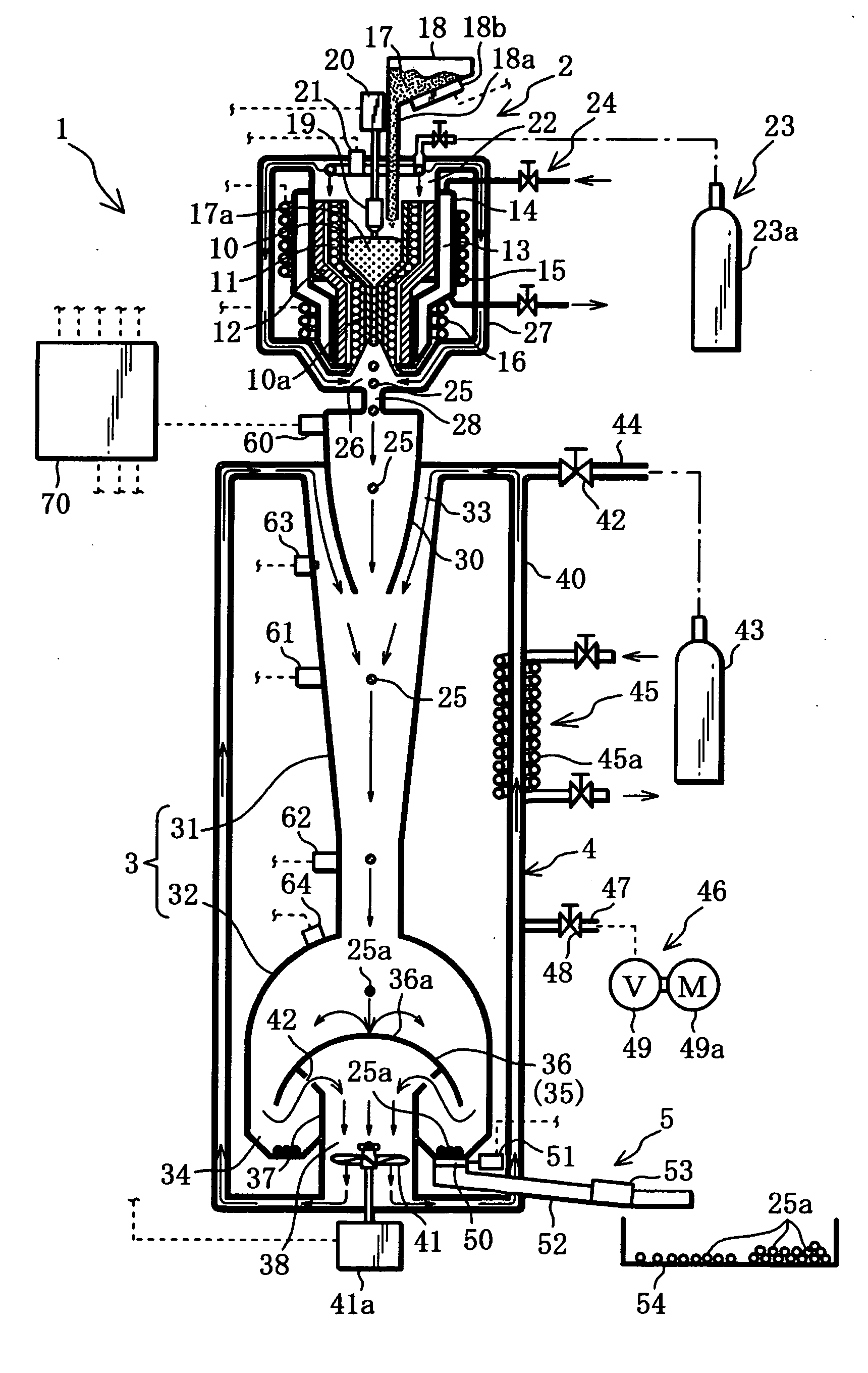
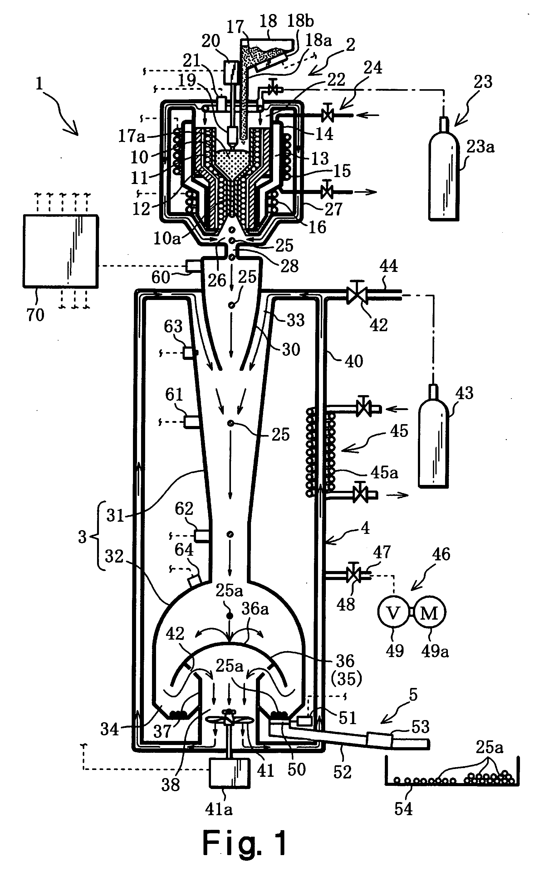
[0013] As above, the particulate melt is cooled by the cooling gas, and since the melt maintains the free fall state where gas resistance is low, the substantially spherical single-crystallized crystalline body can be produced. Further, an impact is applied to the particulate melt brought into the supercooled state by means of the cooling gas to generate the crystalline nucleus, whereby crystal is imposed at once and a crystalline body can be produced. Moreover, in order to effectively cool the melt by means of the cooling gas, the cooling time can be reduced and the height of the drop tube can be significantly shortened, thereby cutting down equipment cost.

Problems solved by technology

In such kind of spherical crystal producing device, a particulate melt is merely cooled by means of radiation cooling, which takes a long cooling time and requires a tall drop tube, thus equipment cost becomes expensive.
Moreover, it is difficult to cool all over the melt evenly.
In a case of a melt of silicon or the like, the melt has a property of expanding when being solidified, thus, cooling the whole melt unevenly distorts the shape of a solidified spherical crystal easily.
Also an external force acts on the falling particulate melt, thus the structure within the melt easily fluctuates, and the shape of the solidified spherical crystal easily distorts.
Thus a single crystal is not necessarily obtained.

Method used


Image

  • Drop tube type granular crystal producing device
  • Drop tube type granular crystal producing device
  • Drop tube type granular crystal producing device

Examples


Embodiment Construction

[0027] Hereinbelow, the best mode for implementing the present invention will be described with reference to the drawings.

[0028] This drop tube type particulate crystalline body producing device melts the raw material of an inorganic material in a crucible, drops the particulate melt from a nozzle, and solidifies a particulate melt while allowing it to free fall inside the drop tube to continuously produce a substantially spherical crystalline body consisting of a single crystal with the inorganic material. The substantially spherical crystalline body has a diameter of approximately 600 to 1500 μm.

[0029] The present embodiment relates to a drop tube type particulate crystalline body producing device 1 as an example, in which a semiconductor is employed as the inorganic material, and p-type or n-type silicon is employed as the semiconductor, to produce a substantially spherical crystalline body with a silicon single crystal.

[0030] As shown in FIG. 1, the drop tube type particulate...


PUM

PropertyMeasurementUnit
Temperatureaaaaaaaaaa
Pressureaaaaaaaaaa
Speedaaaaaaaaaa

Abstract

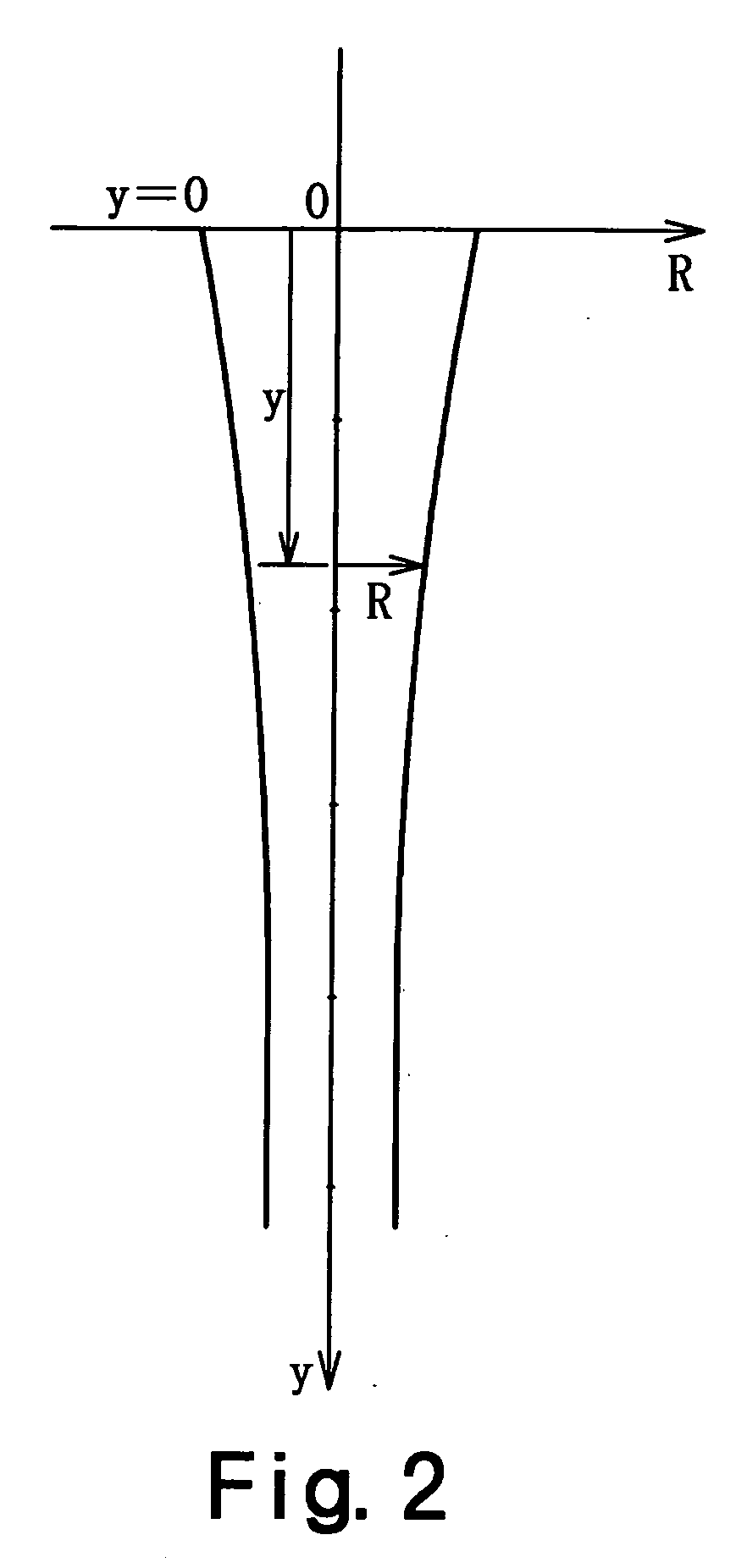
A drop tube type particulate crystalline body producing device is a device for creating a substantially spherical crystalline body by solidifying a particulate melt of an inorganic material while allowing it to free-fall inside a drop tube. This device 1 has a melt formation device 2, drop tube 3, gas flow formation means for forming inside the drop tube 3 a gas flow of cooling gas, and recovery mechanism 5 for recovering a crystalline body 25a from the lower end of the drop tube 3. The drop tube 3 comprises an introducing tube 30, cooling tube 31, and solidification tube 32, where the cooling tube 31 is configured such that the cross sectional area thereof becomes smaller toward the bottom such that the cooling gas flow speed becomes substantially equal to the free fall speed of the particulate melt, and the solidification tube 32 is connected to the lower end of the cooling tube 31 and has a cross sectional area enlarged discontinuously from the lower end of the cooling tube 31. In a proximity of the upper end of the solidification tube 32, the flow speed of the cooling gas is rapidly reduced and the gas pressure increases, whereby a crystal nucleus is generated in the melt in a supercooled state, and the melt is crystallized at once.

Description

TECHNICAL FIELD [0001] The present invention relates to a drop tube type particulate crystalline body producing device for creating a substantially spherical crystalline body by solidifying a particulate melt of an inorganic material while allowing it to free-fall inside a drop tube, and more particularly relates to a drop tube type particulate crystalline body producing device which is configured to flow cooling gas for cooling the falling melt in the same direction as the falling direction of the melt at substantially an equal speed. BACKGROUND OF THE INVENTION [0002] The U.S. Pat. No. 4,322,379 discloses a technology for producing tear-drop shaped crystals of substantially uniform size, in which semiconductor silicon is heated inside the upper end portion of a drop tube made of quartz in order to obtain a melt, the gas pressure of helium gas is caused to act on this melt, and the particulate melt thus obtained is allowed to free-fall inside the drop tube and solidified during the...

Claims


Application Information

Patent Timeline
IPC IPC(8): H01L31/00B01D9/00C30B11/00C30B29/06C30B29/66C30B30/08
CPCB01D9/0013C30B11/00C30B29/06C30B30/08Y10T117/102Y10T117/10Y10S117/901B01D9/0036
Inventor NAKATA
Owner SPHELAR POWER
Learn More