Method and apparatus for liquid microencapsulation with polymers using ultrasonic atomization

a technology of polymer shell and microencapsulation method, which is applied in the field of liquid substrate encapsulation, can solve the problems of volatile core materials, reactive core materials, and toxicity to the environment or to the person handling or administering products, and achieves the effect of facilitating collection of cured capsules and minimizing surface deposition

Inactive Publication Date: 2006-04-06
RGT UNIV OF CALIFORNIA
View PDF7 Cites 45 Cited by
  • Summary
  • Abstract
  • Description
  • Claims
  • Application Information

AI Technical Summary

Benefits of technology

[0026] According to another aspect of the invention, means for electrostatically charging the walls and microcapsules after formation t

Problems solved by technology

Core materials may be volatile, reactive, sensitive to oxidation or chemically incompatible with the surroundings during delivery.
Core materials may also be toxic to the environment or to the person handling or administering the product.
Another disadvantage of emulsion methods is that the newly formed capsules tend to adhere to each other.
The high cost of microencapsulation may limit its use in certain beneficial applications.
One significant contributor to the costs associated with microencapsulation is the number of steps involved in the process.
The cost of the solvents, coacervation agents and shell material that is selected may also cause the cost of microencapsulation to rise.
The complexity of the microencapsu

Method used


Image

  • Method and apparatus for liquid microencapsulation with polymers using ultrasonic atomization
  • Method and apparatus for liquid microencapsulation with polymers using ultrasonic atomization
  • Method and apparatus for liquid microencapsulation with polymers using ultrasonic atomization

Examples


example 1

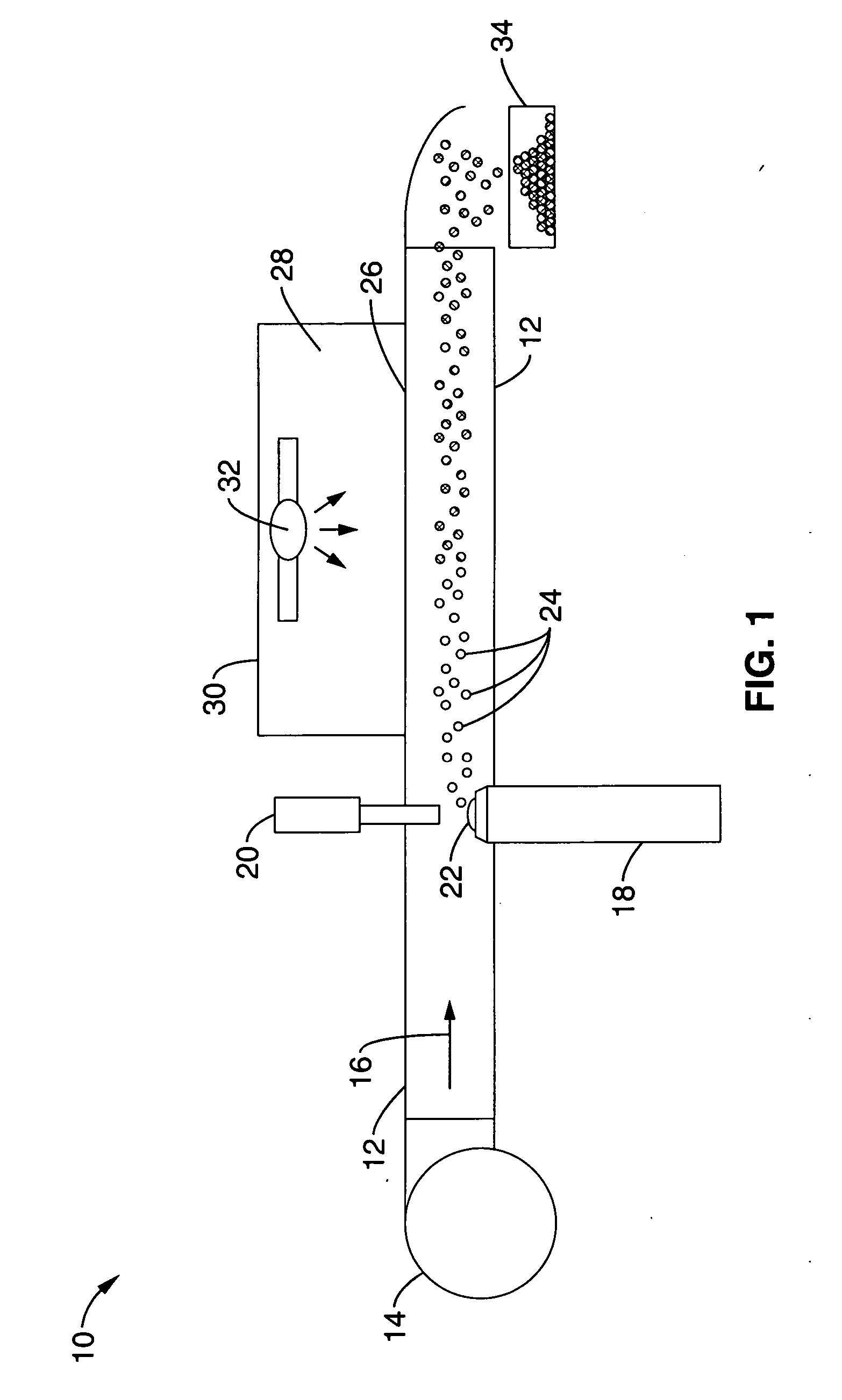
[0077] To demonstrate the viability of the methods and apparatus shown schematically in FIG. 1, a test apparatus was fabricated with a tubular flow channel approximately 18 inches long with a 2×2 inches square cross section made of acrylic plexiglass. A 6″×2″ UV transparent Fotodyne's UviClear top window was added in the region of the continuous UV curing lamp mainly emitting UV light between 260 nm and 460 nm and consuming 400 Watts of electrical power. The window transmits 85% of the UV light at 312 nm. To enhance the illumination inside the channel, the bottom and side walls were covered with highly reflecting aluminum foil. The flow rate in the channel was achieved using a variable controlled transformer (variac) to regulate the air fan. The speed of airflow in the channel was calibrated for the voltage settings of the variac using an anemometer. The flow rate used during the experiments was 2.4 ms−1. The horn ultrasound was a Vibra Cell Model V1A of Sonics and Materials.

[0078]...

example 2

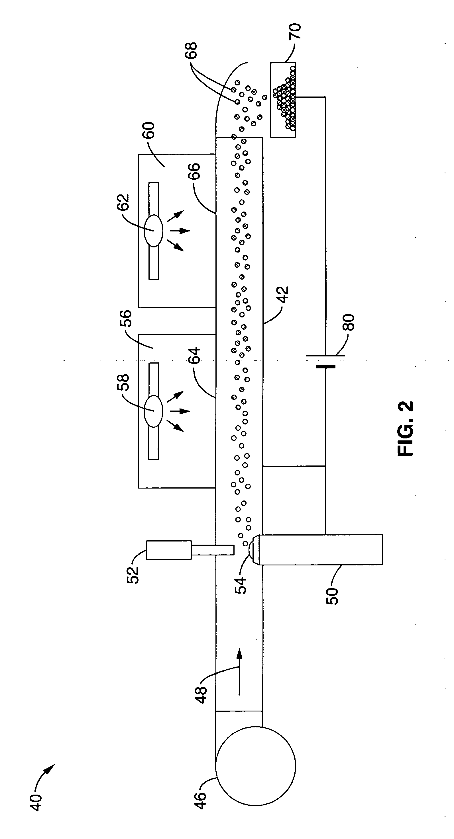
[0082] Another non-limiting example of apparatus and method of the invention was tested using a multi-port injector as a source of microcapsules. The injector head was suspended at the top of a transparent housing with an ultraviolet light source directed into the interior. A collector was at the opposite end of the housing from the injector head and water was used as a trap. Microcapsules formed at the injector head would fall under the forces of gravity through the UV light to the collector.

[0083] In this example, the monomer Propoxylated(2) Neopentyl Glycol Diacrylate (SR-9003) from Sartomer, PA and the photo-initiator Benzil Dimethyl Ketal (Sarcure SR-1120) from Sartomer, PA were used. The monomer solution was prepared by adding 3% by weight photo-initiator to the monomer. The core material that was used was tap water and a surfactant, Tween-80. The water-surfactant solution was prepared by adding 10 ml of Tween-80 to 100 ml of water. A few drops of red ink were added to the wa...


PUM

PropertyMeasurementUnit
Angleaaaaaaaaaa
Diameteraaaaaaaaaa
Diameteraaaaaaaaaa

Abstract

An apparatus and method for encapsulating a liquid or suspension within a polymeric shell to form a microcapsule of a selected size ranging from approximately 0.1 μm to 1000 μm in diameter. The apparatus preferably has a laminar flow of air through a channel and ultrasonic atomizer with the head oriented at approximately ninety degrees from the laminar flow. Emulsions, liquids or thin films of core and shell materials are atomized and the formed microcapsules are exposed to ultraviolet light or additionally infrared light to cure the polymer shell and then are collected. A variety of capsule morphologies can be created by the choice of materials and process conditions to achieve desired controlled or programmed release kinetics. Surface functionalization of the outer shell of the microcapsules capsules can also be achieved to facilitate targeted delivery.

Description

CROSS-REFERENCE TO RELATED APPLICATIONS [0001] This application claims priority from U.S. provisional application Ser. No. 60 / 613,879 filed on Sep. 27, 2004, incorporated herein by reference in its entirety.STATEMENT REGARDING FEDERALLY SPONSORED RESEARCH OR DEVELOPMENT [0002] Not Applicable INCORPORATION-BY-REFERENCE OF MATERIAL SUBMITTED ON A COMPACT DISC [0003] Not Applicable NOTICE OF MATERIAL SUBJECT TO COPYRIGHT PROTECTION [0004] A portion of the material in this patent document is subject to copyright protection under the copyright laws of the United States and of other countries. The owner of the copyright rights has no objection to the facsimile reproduction by anyone of the patent document or the patent disclosure, as it appears in the United States Patent and Trademark Office publicly available file or records, but otherwise reserves all copyright rights whatsoever. The copyright owner does not hereby waive any of its rights to have this patent document maintained in secr...

Claims


Application Information

Patent Timeline
IPC IPC(8): B29C39/10
CPCA61K9/5089B01J13/04B01J13/206B29K2105/0076
Inventor PILON, LAURENT G.BERBEROGLU, HALIL
Owner RGT UNIV OF CALIFORNIA
Why Eureka
Try Eureka