Electrostatic ultrasonic transducer and ultrasonic speaker

an ultrasonic transducer and ultrasonic speaker technology, applied in the direction of electrical transducers, transducer types, electric/electrostrictive transducers, etc., can solve the problems of low sound pressure, high sound speed, and low sound pressure, so as to maintain constant high directionality of reproduced sound and reduce distortion of output waveform to input signal.

Inactive Publication Date: 2006-04-06
SEIKO EPSON CORP
View PDF17 Cites 83 Cited by
  • Summary
  • Abstract
  • Description
  • Claims
  • Application Information

AI Technical Summary

Benefits of technology

[0050] By the configuration, electrostatic forces can be allowed to symmetrically act positively and negatively on the vibrating film by the electrostatic forces acting between the front-side fixed electrode and the vibrating film and between the rear-side fixed electrode and the vibrating film, and thereby, the distortion of the output waveform to the input signal can be made smaller.
[0051] Further, an ultrasonic speaker of the invention is characterized by being provided with a detection fixed electrode for detecting an output waveform of the push-pull type electrostatic ultrasonic transducer in part of the front-side fixed electrode and the rear-side fixed electrode of the push-pull type electrostatic ultrasonic transducer, and including: distortion detection means for detecting distortion of the output waveform based on information of the output waveform of the push-pull type electrostatic ultrasonic transducer detected by the detection fixed electrode; first gain adjustment means for adjusting gain of a power amplifier for front-side fixed electrode for amplifying a driving signal to be supplied to the front-side fixed electrode; second gain adjustment means for adjusting gain of a power amplifier for rear-side fixed electrode for amplifying a driving signal to be supplied to the rear-side fixed electrode; and control means for controlling the first and second gain adjustment means based on the distortion information of the output waveform detected by the distortion detection means so that the distortion of the output waveform of the push-pull type electrostatic ultrasonic transducer may become smaller.
[0052] In the ultrasonic speaker having the above described configuration, a detection fixed electrode for detecting an output waveform of the push-pull type electrostatic ultrasonic transducer in part of the front-side fixed electrode and the rear-side fixed electrode of the push-pull type electrostatic ultrasonic transducer, and the first and second gain adjustment means are controlled to adjust the gain of the power amplifier for front-side fixed electrode and the power amplifier for rear-side fixed electrode by the control means so that the distortion of the output waveform of the push-pull type electrostatic ultrasonic transducer may become smaller (the vibrating film may vibrate faithfully to the input signals).
[0053] Thereby, even in the case where mechanical characteristics and electrical characteristics vary because of aging or the like, the gain of the power amplifier for front-side fixed electrode and the power amplifier for rear-side fixed electrode is automatically adjusted and the ultrasonic wave with low distortion can be output constantly. That is, the directionality of reproduced sound (self-demodulated sound) can be constantly maintained high.

Problems solved by technology

When modulated wave (sound wave) formed by amplitude-modulating ultrasonic carrier wave at high sound pressure with an acoustic signal in an audible band is radiated in the air, because of nonlinearity of air, the sound speed becomes high at the location where the sound pressure is high and becomes low at the location where the sound pressure is low, and distortion occurs in waveform as the sound wave propagates in the air.
It has been known that, as a result, the distortion is accumulated in wave form and the carrier component is gradually attenuated as the sound wave propagates in the air, and the acoustic signal component in the audible band used for modulation is self-demodulated.
However, the conventional ultra-directional speaker is often evaluated as being lower in sound reproduction quality compared to a loudspeaker, and only used for voice application such as local announcement or explanation of exhibition.
Thus, since the resonant ultrasonic transducer has the sound pressure-frequency characteristic in a narrow band and limited drive frequencies, there are problems that the sound reproduction quality is difficult to be improved and the adjustment to the reproduction range is difficult.
Further, since the transducer is sensitive to excessive inputs and elements are easy to break, there is another problem that it requires careful handling.
On the other hand, since the components that contribute to vibration are only the electrostatic attraction force and the resilient restoration force of the film, there is a drawback that the distortion in output waveform becomes larger.
On the other hand, since the sound wave is output through the through hole provided in the fixed electrode, there are drawbacks that the aperture ratio is smaller and the sound pressure is difficult to be secured.
By the way, in the case of using an electrostatic ultrasonic transducer for the ultra-directional speaker, there is a specific problem that, even when ideal amplitude-modulated wave in an ultrasonic wave band is input to the speaker, if the positively and negatively asymmetric distortion of the waveform (carrier wave) output from the ultrasonic transducer is large, the distortion component becomes an audible sound component, audible sound is directly output from the speaker other than the ultrasonic wave component, and the directionality of auditory sense becomes low.
This is because the electrostatic ultrasonic transducer has a sound pressure characteristic in a wide frequency band (when the audible sound itself is directly input, some degree of sound pressure is provided), and a problem specific to the ultrasonic transducer having wide band characteristics.
In this case, when the speaker is provided so as to overhang to the outside of the housing of the projector, there is a problem that realistic sensation is hindered because a person watching screen from the rear side of the projector directly hears not only the sound reflected by the screen but also the sound from the speaker of the projector main body.
On the other hand, there is a problem that realistic sensation is also hindered because the sound wave radiated from the speaker rear surface is reflected on the rear wall and a person watching screen in front of the projector hears not only the sound reflected by the screen but also the same sound from the rear side.
However, the sound wave reflected at a point-blank range of the housing or internal structure directly bounces back to the vibrating film of the ultrasonic transducer and disturbs the vibration of the vibrating film.
As a result, there is a problem that the directionality and sound quality of sound wave output from the front surface becomes deteriorated.

Method used


Image

  • Electrostatic ultrasonic transducer and ultrasonic speaker
  • Electrostatic ultrasonic transducer and ultrasonic speaker
  • Electrostatic ultrasonic transducer and ultrasonic speaker

Examples


first embodiment

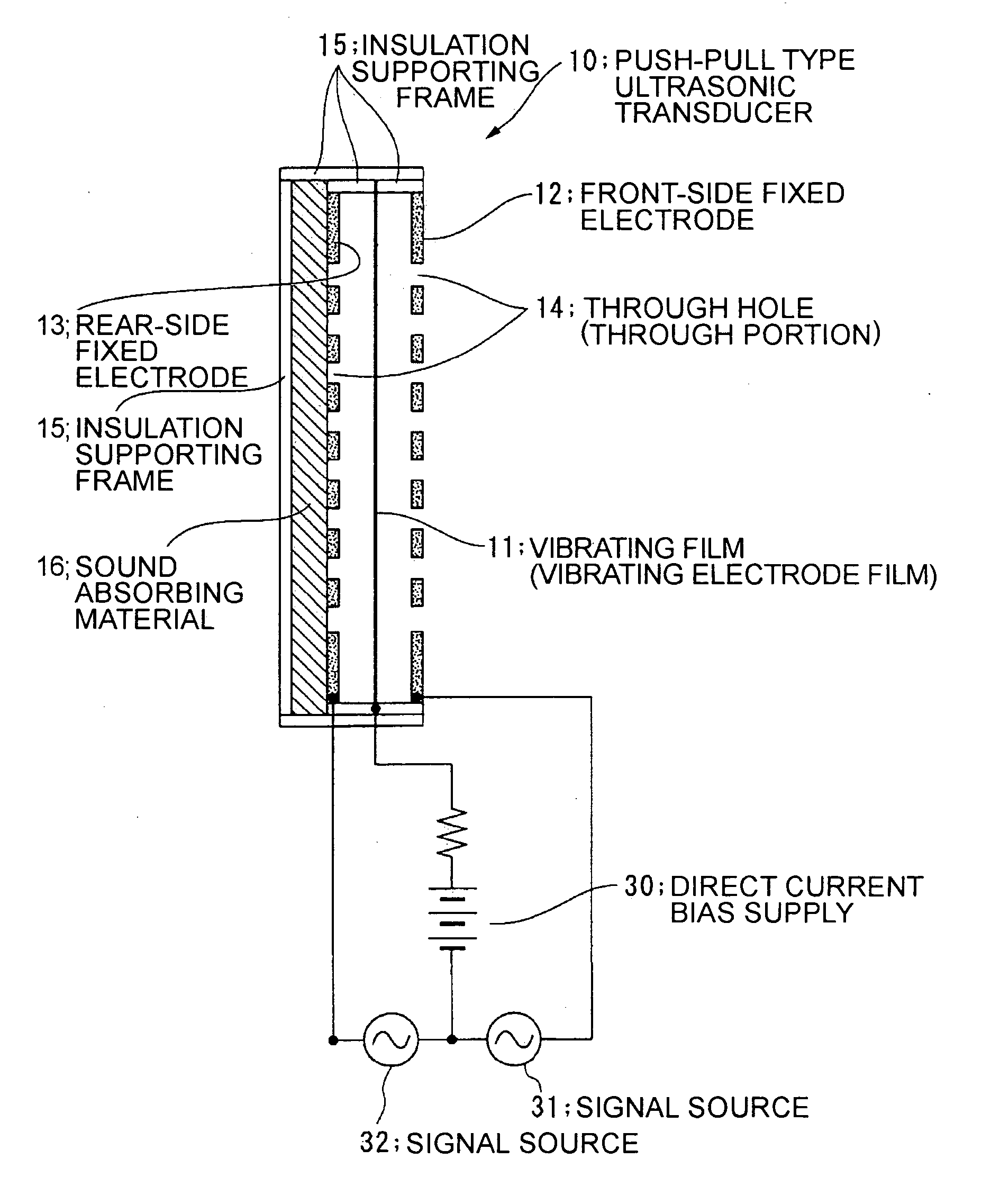
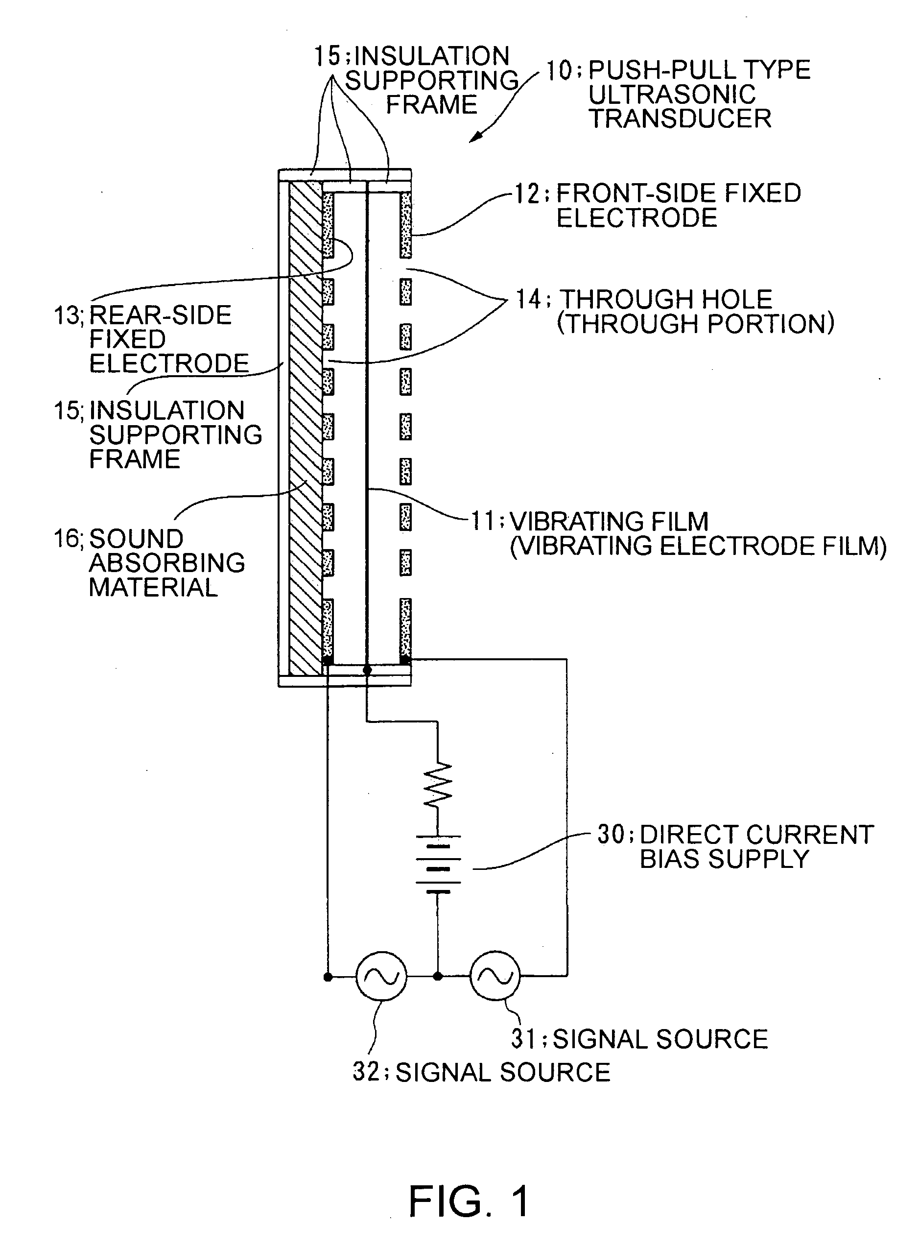
[0066] In FIG. 1, the electrostatic ultrasonic transducer according to the invention has a vibrating film (vibrating electrode film) 11 having a conductive layer and a pair of fixed electrodes of a front-side fixed electrode 12 and a rear-side fixed electrode 13 provided facing the respective surfaces of the vibrating film 11. The vibrating film 11 may be formed by sandwiching the conductive layer (conducting film) that forms an electrode between insulating films or the entire vibrating film 11 may be formed by a conductive material.

[0067] Further, plural through holes 14 are provided in the front-side fixed electrode 12 that sandwiches the vibrating film 11 and plural through holes 14 having the same shapes are provided in the rear-side fixed electrode 13 in positions facing the respective through holes 14 provided in the front-side fixed electrode 12. The front-side fixed electrode 12, the rear-side fixed electrode 13, and the vibrating film 11 are supported in a condition in whic...

second embodiment

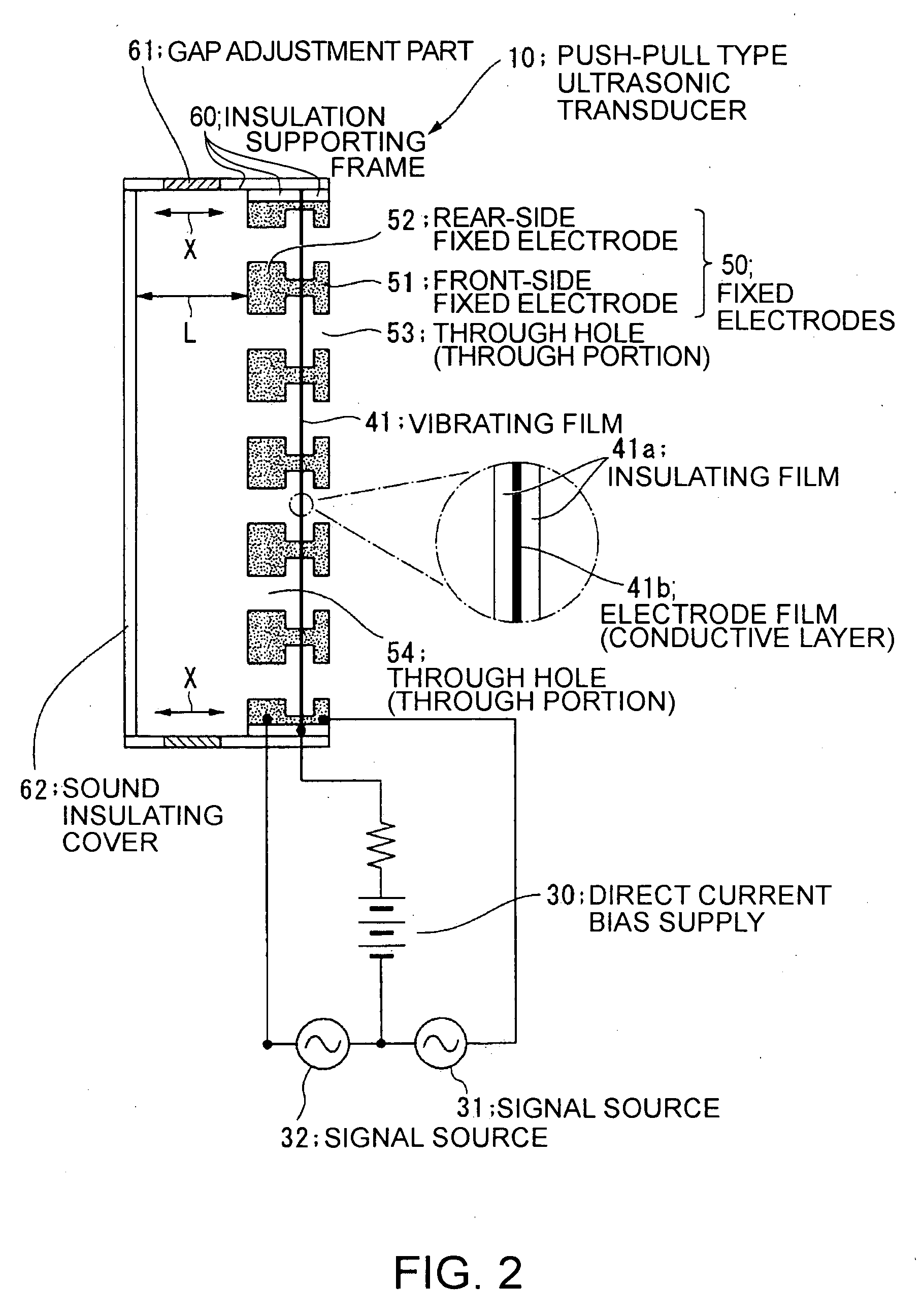
[0073] In FIG. 2, the electrostatic ultrasonic transducer according to the invention has a vibrating film 41 having a conductive layer and a pair of fixed electrodes 50 of a front-side fixed electrode 51 and a rear-side fixed electrode 52 provided facing the respective surfaces of the vibrating film 41.

[0074] The vibrating film 41 is formed by sandwiching the conductive layer (conducting film) 41b that forms an electrode between insulating films 41a. Further, only the parts of the front-side fixed electrode 51 and the rear-side fixed electrode 52 in contact with the vibrating film 41 may be formed by insulating members and the entire vibrating film 41 may be formed by a conductive material.

[0075] Further, plural through holes (through portions) 53 are provided in the front-side fixed electrode 51 that sandwiches the vibrating film 41 and plural through holes (through portions) 54 having the same shapes are provided in the rear-side fixed electrode 52 in positions opposed to the res...

third embodiment

[0104] In FIG. 4, the configuration of the electrostatic ultrasonic transducer according to the invention has a vibrating film (vibrating electrode film) 71 having a conductive layer and a pair of fixed electrodes of a front-side fixed electrode 81 and a rear-side fixed electrode 82 provided facing the respective surfaces of the vibrating film 71. The vibrating film 71 may be formed by sandwiching the conductive layer (conducting film) that forms an electrode between insulating films or the entire vibrating film 71 may be formed by a conductive material.

[0105] Further, plural through holes 83 are provided in the front-side fixed electrode 81 that sandwiches the vibrating film 71 and the rear-side fixed electrode 82 is formed as a solid electrode provided with no through hole. For the rear-side fixed electrode 82, porous metal such as Ni is used. The porous electrode has innumerable air holes on the order from sub-micrometers to several tens of micrometers and is able to absorb ultra...


PUM


Abstract

To provide an electrostatic ultrasonic transducer arranged so that sound wave is not radiated from the rear surface while utilizing advantages of a push-pull type electrostatic ultrasonic transducer.
A push-pull type electrostatic ultrasonic transducer includes a vibrating film 11 having a conductive layer and a pair of fixed electrodes 12, 13 provided facing respective surfaces of the vibrating film, and applies a direct current bias voltage to the conductive layer of the vibrating film and applies an alternating current signal between the pair of fixed electrodes so as to allow the vibrating film to generate sound wave and outputting the sound wave generated from the vibrating film from two sound wave output surfaces via through holes provided in the respective pair of fixed electrodes. Plural through holes are provided in the front-side fixed electrode that sandwiches the vibrating film and through holes having the same shapes are provided in the rear-side fixed electrode in positions opposed to the respective through holes provided in the front-side fixed electrode, and a sound absorbing material 16 is provided facing the rear-side fixed electrode.

Description

BACKGROUND [0001] 1. Technical Field [0002] The present invention relates to an electrostatic ultrasonic transducer and an ultrasonic speaker using the transducer, and specifically, to an electrostatic ultrasonic transducer arranged so as to absorb sound wave output to the rear side of a push-pull type ultrasonic transducer and emit sound wave only from the front side thereof and an ultrasonic speaker using the transducer. [0003] 2. Related Art [0004] When modulated wave (sound wave) formed by amplitude-modulating ultrasonic carrier wave at high sound pressure with an acoustic signal in an audible band is radiated in the air, because of nonlinearity of air, the sound speed becomes high at the location where the sound pressure is high and becomes low at the location where the sound pressure is low, and distortion occurs in waveform as the sound wave propagates in the air. It has been known that, as a result, the distortion is accumulated in wave form and the carrier component is grad...

Claims


Application Information

Patent Timeline
Patent Type & Authority Applications(United States)
IPC IPC(8): H04R19/02H04R19/00
CPCH04R19/02H04R2217/03
Inventor MIYAZAKI, SHINICHI
Owner SEIKO EPSON CORP
Why Eureka
Try Eureka