TCP host

a host and host technology, applied in the field of tcp hosts, can solve the problems of reducing the available memory bus bandwidth, adding latency to the time of data, and high cost of finding the appropriate process and copying data

Active Publication Date: 2006-04-06
MARVELL ASIA PTE LTD
View PDF2 Cites 167 Cited by
  • Summary
  • Abstract
  • Description
  • Claims
  • Application Information

AI Technical Summary

Benefits of technology

[0011] Remote Direct Memory Access (RDMA) eliminates the need for copying received user data between the network protocol stack in kernel space and application buffers in application space in host memory. RDMA avoids this copy by allowing the sender to identify data to be placed directly into application buffers (buffers in user space) and transmitting the identification with the data so that the receiver of the data can place the data directly into the application buffers when it is received.
[0013] The present approach provides a network services processor that includes direct DMA to / from a host system application user space which improves host performance in a non-RDMA capable host system and allows the ability to handle a large number of concurrent TCP connections and high data throughput.
[0015] The socket may be a Transmission Control Protocol socket or a User Datagram Protocol socket. Furthermore, processing bandwidth is reduced by the need to copy the data from kernel space to application space in host memory. In order to reduce the overhead, the present invention provides a mechanism for direct data placement through the use of a virtual queue. Data transferred over the network may be transferred directly between local memory and application space in host memory in the host system or may be indirectly transferred between local memory and application memory in host memory in the host system via kernel space in the host memory.

Problems solved by technology

Finding the appropriate process and copying data is very expensive.
The overhead for copying reduces the available memory bus bandwidth and adds latency to when the data is available for use by the application.

Method used


Image

  • TCP host
  • TCP host
  • TCP host

Examples


Embodiment Construction

[0034] A description of preferred embodiments of the invention follows.

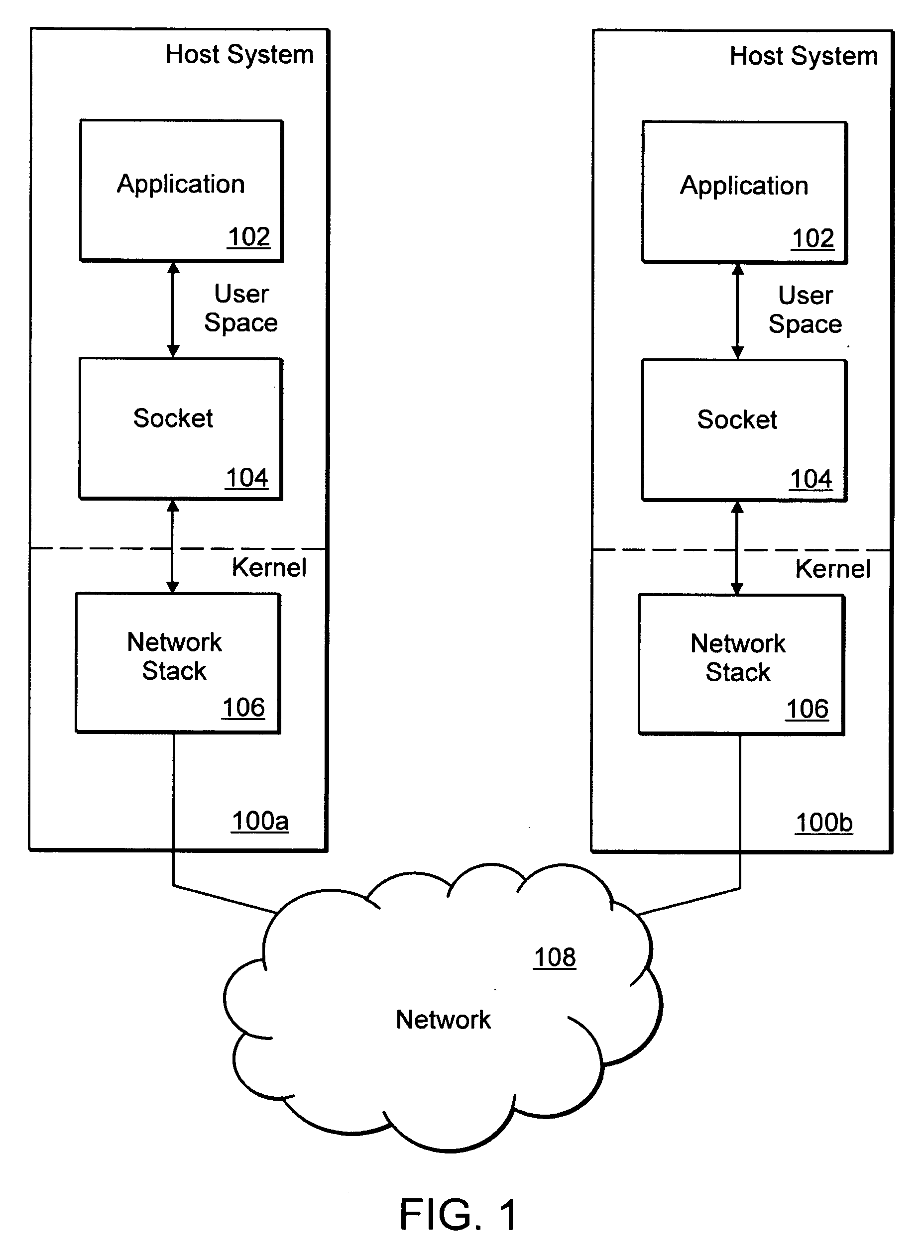
[0035]FIG. 1 is a block diagram illustrating software modules in host systems (hosts) 100a, 100b that are coupled to a network 108. The software modules are used to transfer data between applications executing in the hosts 100a, 100b over a TCP / IP connection. Data is transferred between the applications 102 executing in the hosts through a socket module 104, a network stack 106 and the network 108.

[0036] As is well-known to those skilled in the art, the Open System Interconnection (OSI) reference model defines seven network protocol layers (L1-L7). The physical layer (L1) represents the actual interface, electrical and physical that connects a device to a transmission medium. The data link layer (L2) performs data framing. The network layer (L3) formats the data into packets. The transport layer (L4) handles end to end transport. The session layer (L5) manages communications between devices, for example, whethe...


PUM


Abstract

A network application executing on a host system provides a list of application buffers in host memory stored in a queue to a network services processor coupled to the host system. The application buffers are used for storing data transferred on a socket established between the network application and a remote network application executing in a remote host system. Using the application buffers, data received by the network services processor over the network is transferred between the network services processor and the application buffers. After the transfer, a completion notification is written to one of the two control queues in the host system. The completion notification includes the size of the data transferred and an identifier associated with the socket. The identifier identifies a thread associated with the transferred data and the location of the data in the host system.

Description

RELATED APPLICATIONS [0001] This application claims the benefit of U.S. Provisional Application No. 60 / 669,742, filed on Apr. 8, 2005 and 60 / 609,211, filed on Sep. 10, 2004. The entire teachings of the above applications are incorporated herein by reference.BACKGROUND OF THE INVENTION [0002] The Open Systems Interconnection (OSI) Reference Model defines seven network protocol layers (L1-L7) used to communicate over a transmission medium. The upper layers (L4-L7) represent end-to-end communications and the lower layers (L1-L3) represent local communications. [0003] Networking application aware systems need to process, filter and switch a range of L3 to L7 network protocol layers, for example, L7 network protocol layers such as, HyperText Transfer Protocol (HTTP) and Simple Mail Transfer Protocol (SMTP), and L4 network protocol layers such as Transmission Control Protocol (TCP) and User Datagram Protocol (UDP). In addition to processing the network protocol layers, the networking appl...

Claims


Application Information

Patent Timeline
Patent Type & Authority Applications(United States)
IPC IPC(8): G06F15/16
CPCH04L49/90H04L49/901H04L49/9031H04L49/9063H04L69/16H04L69/163H04L69/162H04L69/165
Inventor HUSSAIN, MUHAMMAD R.KESSLER, RICHARD E.MASOOD, FAISALSANZONE, ROBERT A.BADR, IMRAN
Owner MARVELL ASIA PTE LTD
Why Eureka
Try Eureka