Transmission electron microscope and image observation method using it

a technology of electron microscope and image observation method, which is applied in the direction of instruments, heat measurement, machines/engines, etc., can solve the problems of image drift, thermal, mechanical and electrical stability, and shape distortion

Inactive Publication Date: 2006-04-13
HITACHI HIGH-TECH CORP
View PDF10 Cites 18 Cited by
  • Summary
  • Abstract
  • Description
  • Claims
  • Application Information

AI Technical Summary

Benefits of technology

[0012] An object of the invention is to solve the problem in the background art and to correct drift generated at the time of photographing a TEM image simultaneously with photographing to thereby provide a TEM image free from influence of drift.

Problems solved by technology

Image drift is an issue on this occasion.
A chief cause of image drift is thermal, mechanical and electrical stability.
A factor of thermal instability is shape distortion due to temperature changes of a mirror body, a specimen holder and a specimen itself.
Causes of the temperature change of the specimen itself are deformation, damage, and so on, due to change in density of applied electron beams.
The latter shifts a resonance point with the mirror body to make it difficult to transmit floor vibration directly.
The simplest method is to wait for termination of specimen drift but a long time is taken and it is inconvenient to wait for termination of drift whenever the position of the specimen is changed.
If preparation cannot be made from the previous day, a considerably long time is required for termination of drift.
The manipulation mechanism using the piezoelectric element for correcting change in air pressure cannot be fit to drift caused by other factors.
If photographing is performed in a short time and development is performed for a long time, the negative film becomes so “hard” that the image becomes rough.
If a high-luminance electron gun is mounted in order to obtain sufficient degree of darkness, there is the possibility that the specimen may be damaged because of high applied electron beam density.
The method of correcting drift by the manipulation mechanism using the piezoelectric element is not effective for drift out of uniform rate.
The method of correcting drift due to through-focusing by the image shift coil cannot be applied to general drift.
The method of photographing the TEM image as a video image cannot be applied to the photographic film as well as much labor is taken for correction.
The method of calculating view field difference between the plurality of TEM images and correcting specimen drift cannot correct drift generated while each TEM image is photographed.
The method of taking the TEM image in by the TV camera disposed above the fluorescent screen and detecting and correcting drift cannot detect drift because the TEM image does not appear above the fluorescent screen when the TEM image is recorded.

Method used


Image

  • Transmission electron microscope and image observation method using it
  • Transmission electron microscope and image observation method using it
  • Transmission electron microscope and image observation method using it

Examples


first embodiment

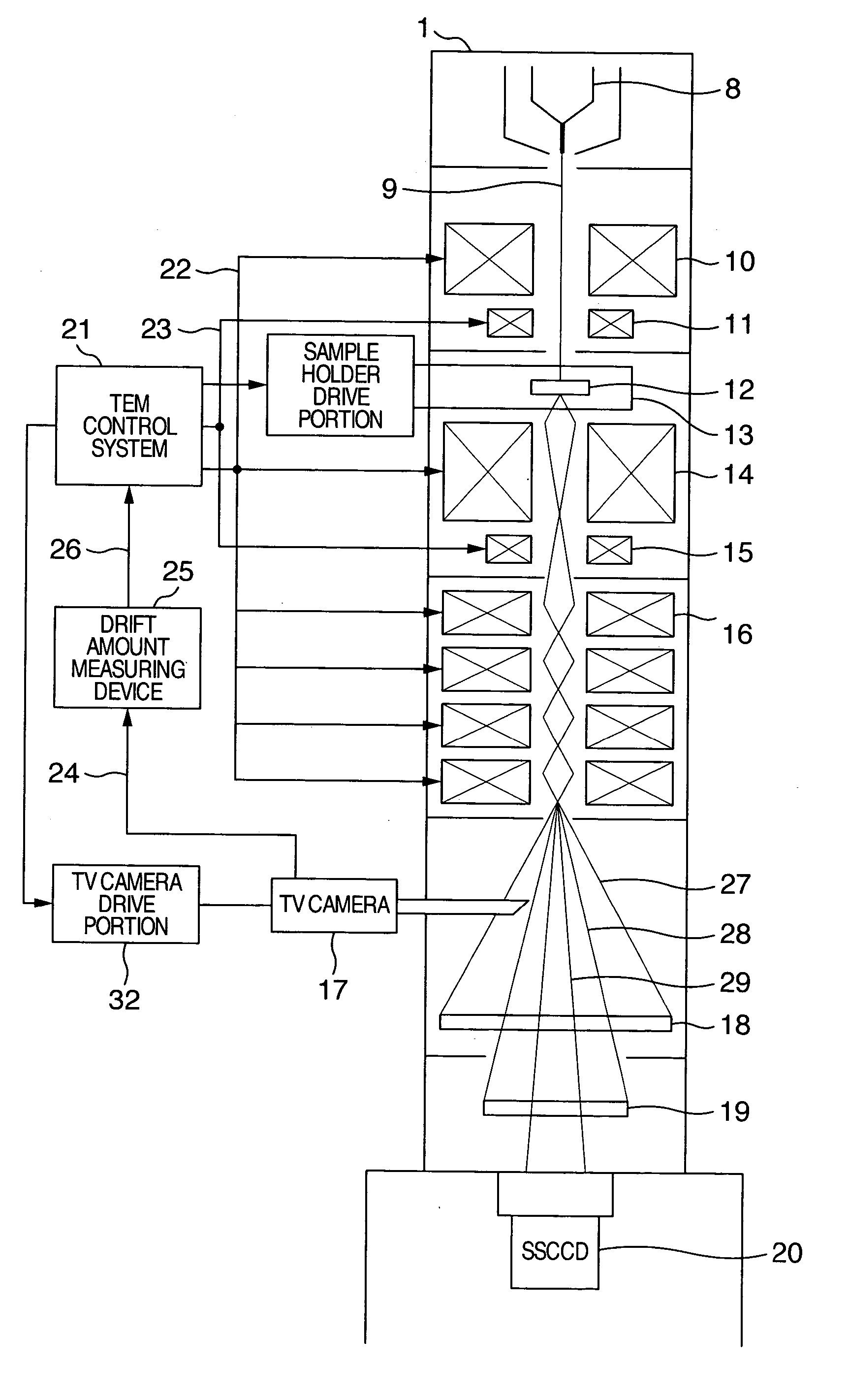
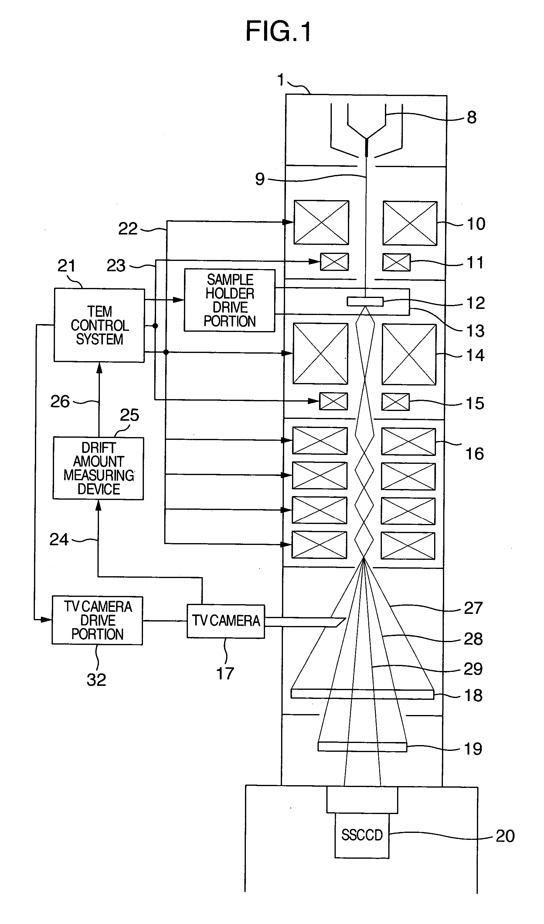
[0025]FIG. 1 is a block diagram showing a transmission electron microscope according to the invention. An electron beam 9 generated in an electron gun 8 is applied onto a specimen 12 by a converging lens 10. The position and angle of irradiation can be adjusted by a deflection coil 11. A transmission electron image of the specimen 12 is magnified by an objective lens 14 and intermediate / projection lenses 16, so that the transmission electron image can be observed on an observation fluorescent screen 18. The specimen 12 to be observed is fixed into a specimen holder 13, so that the view field of observation can be adjusted by movement of the specimen holder 13. If an image shift coil 15 is used, the view field of observation can be adjusted electromagnetically without movement of the specimen holder 13. A TEM control system 21 controls all lens systems, electron beam deflection systems and specimen manipulation systems.

[0026] The view field 27 of the observation fluorescent screen is...

second embodiment

[0034] A method using the second embodiment for recording a TEM image not affected by drift will be described with reference to FIG. 4 which is a flow chart showing a specific procedure. First, the view field of observation is searched (S31) so that a specimen is moved into the view field 28 of the photographic film or the view field 29 of the SSCCD. Then, the PSD 30 is inserted in a region of the view field 27 of the observation fluorescent screen except the view field 28 of the photographic film and the view field 29 of the SSCCD (S32). When the PSD 30 is located out of view field in which drift can be detected, for example, when the PSD 30 is in the place where the specimen is not provided or in a portion of a mesh frame, the voltage signal from the PSD becomes unstable or comes out of the center of the voltage range. In such a case (S33), the PSD 30 is moved by the PSD drive portion 33 (S34) so that the output voltage comes to the nearly center of the voltage range stably. If th...


PUM


Abstract

Drift generated at the time of photographing a TEM image is corrected simultaneously with photographing, so that a TEM image free form influence of drift is photographed. While the TEM image is recorded, drift in the place out of the view field subjected to recording is measured from moment to moment by another TV camera or a position sensitive detector. Drift is corrected by the movement of the specimen due to a specimen holder or by the movement of the image due to an image shift coil.

Description

BACKGROUND OF THE INVENTION [0001] The present invention relates to a transmission electron microscope and an image observation method using it and particularly relates to a transmission electron microscope capable of observation of an image not affected by drift and an image observation method using the transmission electron microscope. [0002] A transmission electron microscope (TEM) is an apparatus using electron beams for directly observing a fine structure of a specimen and has far higher resolving power than that of an optical microscope so that the TEM can perform atomic-level structure analysis. The TEM is an apparatus indispensable nowadays for the medical and biological field and the metallic and semiconductor material field. Because a technique for observing a specimen while heating / cooling it has been developed, the TEM has been highly recognized to be not only an observation apparatus but also an on-site experimental apparatus. [0003] To perform atomic-level structure an...

Claims


Application Information

Patent Timeline
Patent Type & Authority Applications(United States)
IPC IPC(8): G21K7/00
CPCH01J37/224H01J37/26H01J37/265H01J2237/0216H01J2237/2025H01J2237/20292
Inventor TANIGUCHI, YOSHIFUMIOTSUKA, HISAFUMI
Owner HITACHI HIGH-TECH CORP
Why Eureka
Try Eureka