Motor drive apparatus having oscillation-reducing control function for output torque

a technology of output torque and control function, which is applied in the direction of electric controllers, dynamo-electric converter control, dynamo-electric gear control, etc., can solve the problems of reducing the control response of wave control system and overmodulation control system, unable to obtain sufficient power output, and limited voltage utilization factor, so as to reduce the oscillation of output torque

Inactive Publication Date: 2006-04-13
TOYOTA JIDOSHA KK
View PDF5 Cites 34 Cited by
  • Summary
  • Abstract
  • Description
  • Claims
  • Application Information

AI Technical Summary

Benefits of technology

[0029] An object of the present invention is to provide a motor drive apparatus that can

Problems solved by technology

A resultant problem is that the voltage utilization factor is limited and accordingly a sufficiently high power output cannot be obtained.
However, the rectangular-wave control system and overmodulation control system are relatively lower in control response than the PWM control system.
A resultant problem is that, when a sudden change occurs in torque command value or mot

Method used


Image

  • Motor drive apparatus having oscillation-reducing control function for output torque
  • Motor drive apparatus having oscillation-reducing control function for output torque
  • Motor drive apparatus having oscillation-reducing control function for output torque

Examples


first embodiment

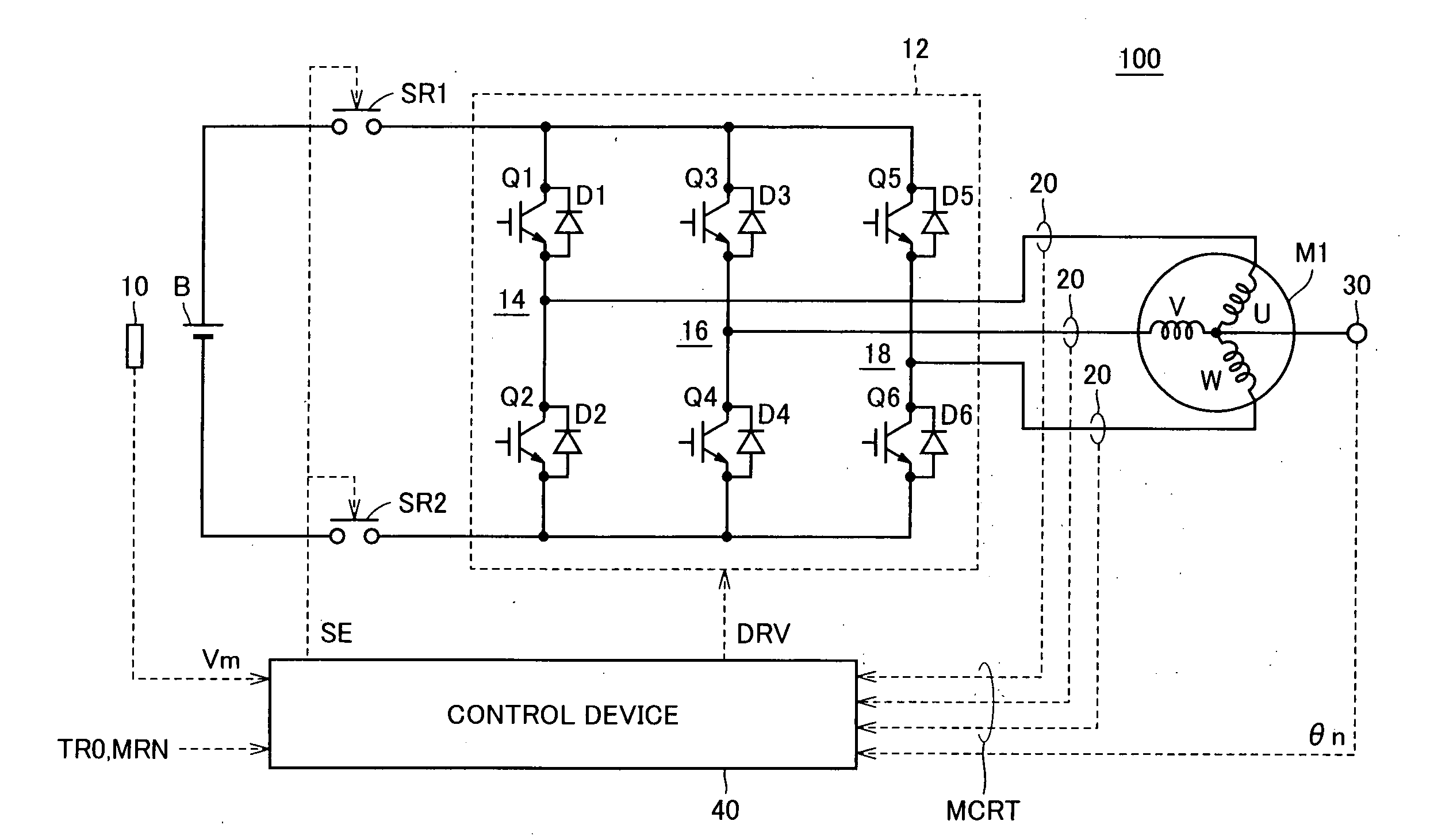
[0069]FIG. 1 is a schematic block diagram of a motor drive apparatus according to a first embodiment of the present invention.

[0070] Referring to FIG. 1, motor drive apparatus 100 includes a DC power supply B, a voltage sensor 10, an inverter 12, an electric-current sensor (hereinafter current sensor) 20, a resolver 30, and a control device 40.

[0071] An AC motor M1 is a drive motor for generating torque to drive the drive wheels of a hybrid vehicle or electric vehicle. AC motor M1 also operates as an electric generator driven by an engine as well as an electric motor for the engine and thus have the ability to start the engine for example.

[0072] Inverter 12 is comprised of a U phase arm 14, a V phase arm 16 and a W phase arm 18. U phase arm 14, V phase arm 16 and W phase arm 18 are provided in parallel between a power supply line and a ground line.

[0073] U phase arm 14 is comprised of series-connected NPN transistors Q1, Q2. V phase arm 16 is comprised of series-connected NPN tr...

second embodiment

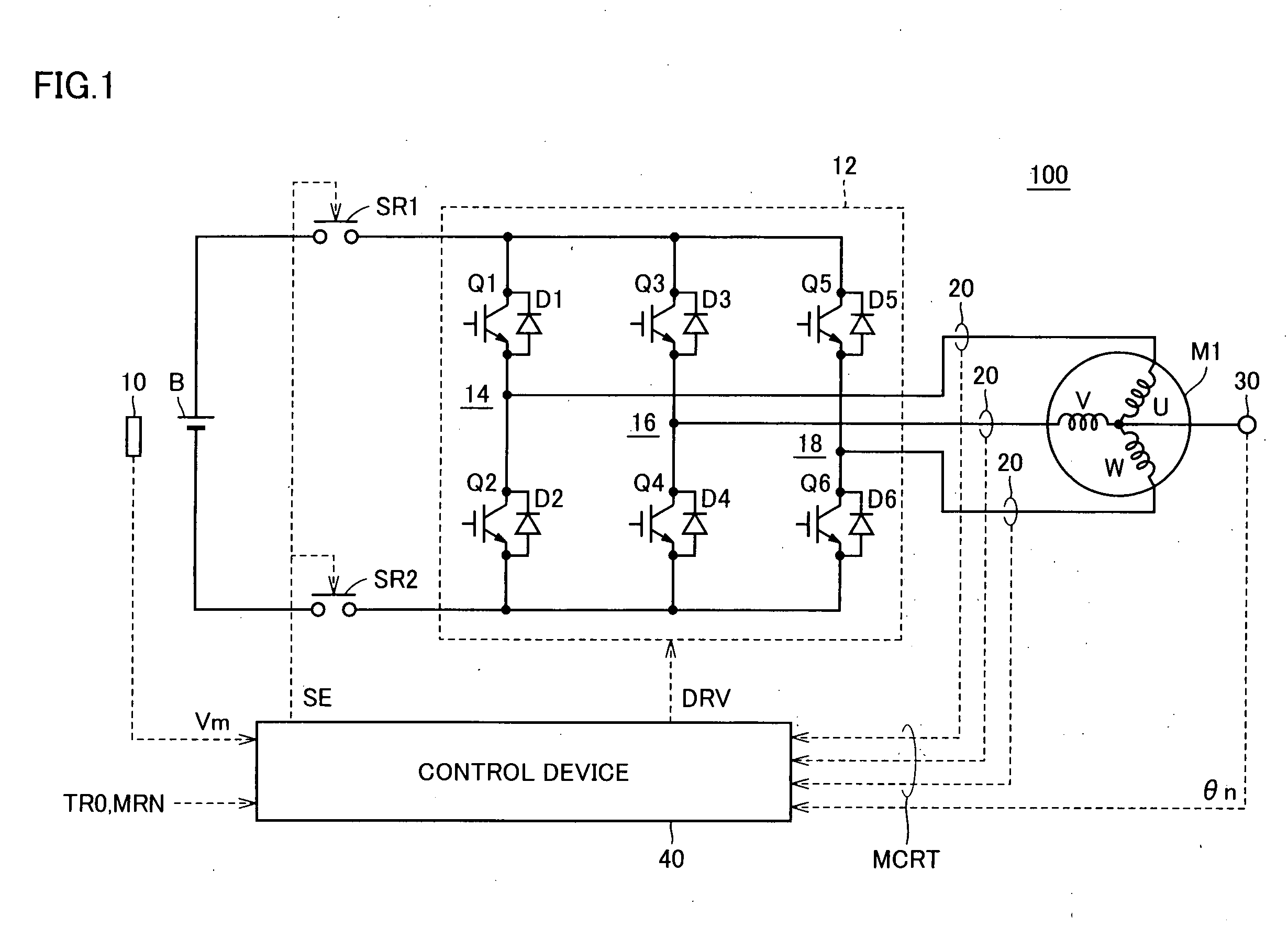
[0156] As described above in connection with the first embodiment, oscillation-reducing control means 501 of the present invention generates oscillation-reducing torque Δtr based on an anti-phase component of revolution number varying component ΔMRN of motor revolution number MRN. Inverter control means 502 adds the generated oscillation-reducing torque Δtr to externally provided torque command value TR0 and the sum is used as final torque command value TR for driving AC motor M1. Thus, oscillations of the output torque of AC motor M1 can be reduced and ride comport can be implemented. In particular, the oscillation-reducing control is effective in such a case where there is any trigger causing vibrations of the vehicle, for example, where torque command value TR0 of AC motor M1 suddenly changes.

[0157] However, when the vehicle is in a normal-running state or stopped and load-free state, any subtle change in output torque results in any behavior of the vehicle and thus the oscillat...

third embodiment

[0183] In the second embodiment described above, the description is given of the method of applying the oscillation-reducing control in the case where an amount of variation in drive torque exerted on the drive wheels is large.

[0184] As described in connection with FIGS. 13A-13C, the amount of variation in drive torque that is output from motor generator MG2 changes in magnitude depending on the state of the vehicle.

[0185] Accordingly, when the oscillation-reducing control is carried out, the magnitude of the oscillation-reducing torque may be changed depending on the variation amount of the drive torque so as to enhance the effects of the oscillation-reducing control.

[0186] Specifically, when the variation amount of the drive torque is relatively large, oscillation-reducing torque correction unit 62 of oscillation-reducing control means 501 makes a correction by multiplying oscillation-reducing torque Δtr0 by a relatively large correction coefficient Km. For example, when the en...


PUM


Abstract

Under oscillation-reducing control executed while PWM control is performed, an oscillation-reducing torque that is opposite in phase to a varying component of the motor revolution number is generated and, a final torque command value that is the sum of the oscillation-reducing torque and a torque command value is used to drive an AC motor. In a transition state where the PWM control mode is switched to overmodulation control mode, the oscillation-reducing torque that is determined by multiplying an oscillation-reducing torque by a correction coefficient that varies depending on a modulation factor gradually decreases as the correction coefficient decreases and substantially becomes zero when the control mode is switched. Thus, the oscillation-reducing torque has no stepped portion that occurs in the oscillation-reducing torque when the control mode is switched. Thus, oscillations in output torque of the AC motor can be reduced.

Description

[0001] This nonprovisional application is based on Japanese Patent Application Nos. 2004-295076 and 2004-337804 filed with the Japan Patent Office on Oct. 7, 2004 and Nov. 22, 2004, respectively, the entire contents of which are hereby incorporated by reference. BACKGROUND OF THE INVENTION [0002] 1. Field of the Invention [0003] The present invention relates to a motor drive apparatus, and particularly to a motor drive apparatus having an oscillation-reducing control function for output torque. [0004] 2. Description of the Background Art [0005] Hybrid vehicles and electric vehicles have recently been of great interest as environment-friendly motor vehicles. A hybrid vehicle has, as its motive power sources, a DC (direct current) power supply, an inverter and a motor driven by the inverter in addition to a conventional engine. More specifically, the engine is driven to secure the motive power source and a DC voltage from the DC power supply is converted by the inverter into an AC (al...

Claims


Application Information

Patent Timeline
IPC IPC(8): H02P7/00B60L50/16H02P21/00H02P21/05H02P21/14H02P21/18H02P21/22H02P21/24H02P21/28H02P23/04H02P23/14H02P27/06H02P27/08
CPCH02P25/088H02P25/098
Inventor YAGUCHI, HIDEAKI
Owner TOYOTA JIDOSHA KK
Why Eureka
Try Eureka