Superconducting wire and superconducting coil employing it

a superconducting coil and superconducting wire technology, applied in the direction of superconducting magnets/coils, superconductor devices, magnetic bodies, etc., can solve the problems of loss increase, and achieve the effect of reducing the operating cost of a superconducting coil and improving thermal stability

Active Publication Date: 2006-04-13
KISU TAKANOBU +4
View PDF0 Cites 24 Cited by
  • Summary
  • Abstract
  • Description
  • Claims
  • Application Information

AI Technical Summary

Benefits of technology

[0028] As the embodiment for the invention according to claim 1 above, the inventions described in claims 2-4 are preferable. Specifically, the superconducting wires according to claim 1 above wherein a normal conducting metal layer is formed on the superconducting film formed on the substrate, and the parallel conductors electrically separate both the metallic layer and the superconducting film in order to arrange them in parallel (invention according to claim 2). This structure enables to contain the A.C. loss and to improve thermal stability.
[0029] And in the superconducting wires according to claims 1 or 2 above, the parts that electrically separate the parallel conductors are slit-shaped grooves, which is filled with an electrically insulating material, and

Problems solved by technology

Due to the alternate formation of the normal conducting film part and the superconducting film part, ho

Method used


Image

  • Superconducting wire and superconducting coil employing it
  • Superconducting wire and superconducting coil employing it
  • Superconducting wire and superconducting coil employing it

Examples


Embodiment Construction

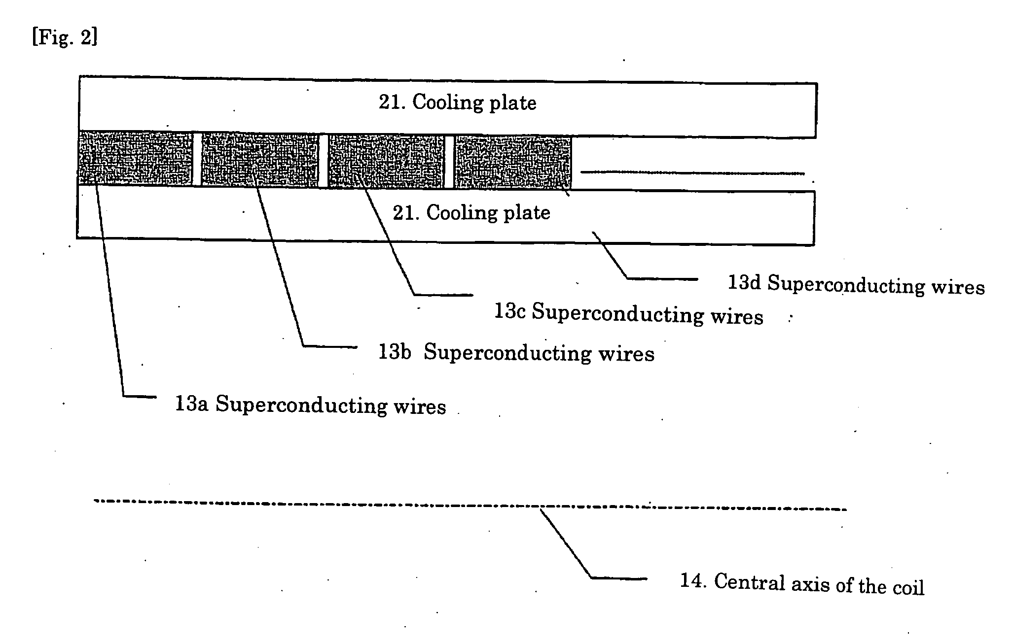
[0062] The embodiments of the present invention will be described with reference to drawings. In the first place, the basic structure of the superconducting wire of the present invention and the application of this wire to superconducting coils will be described with reference to FIGS. 1 and 2.

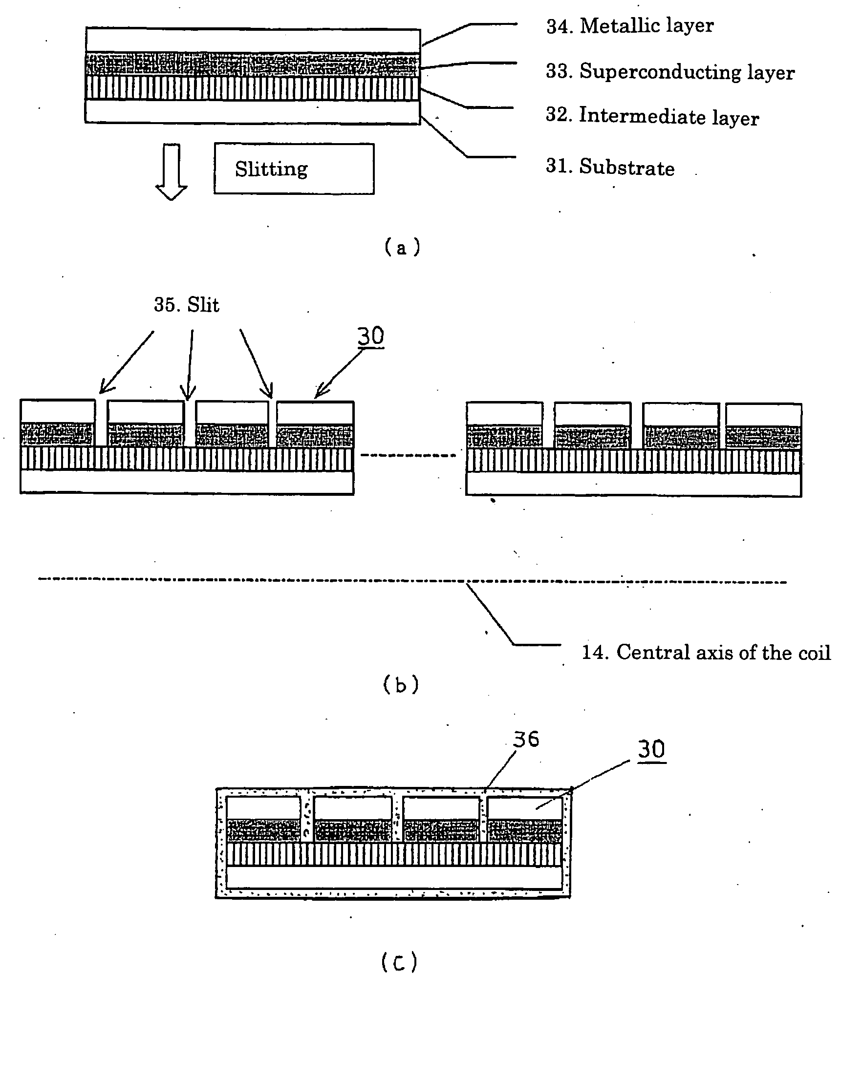
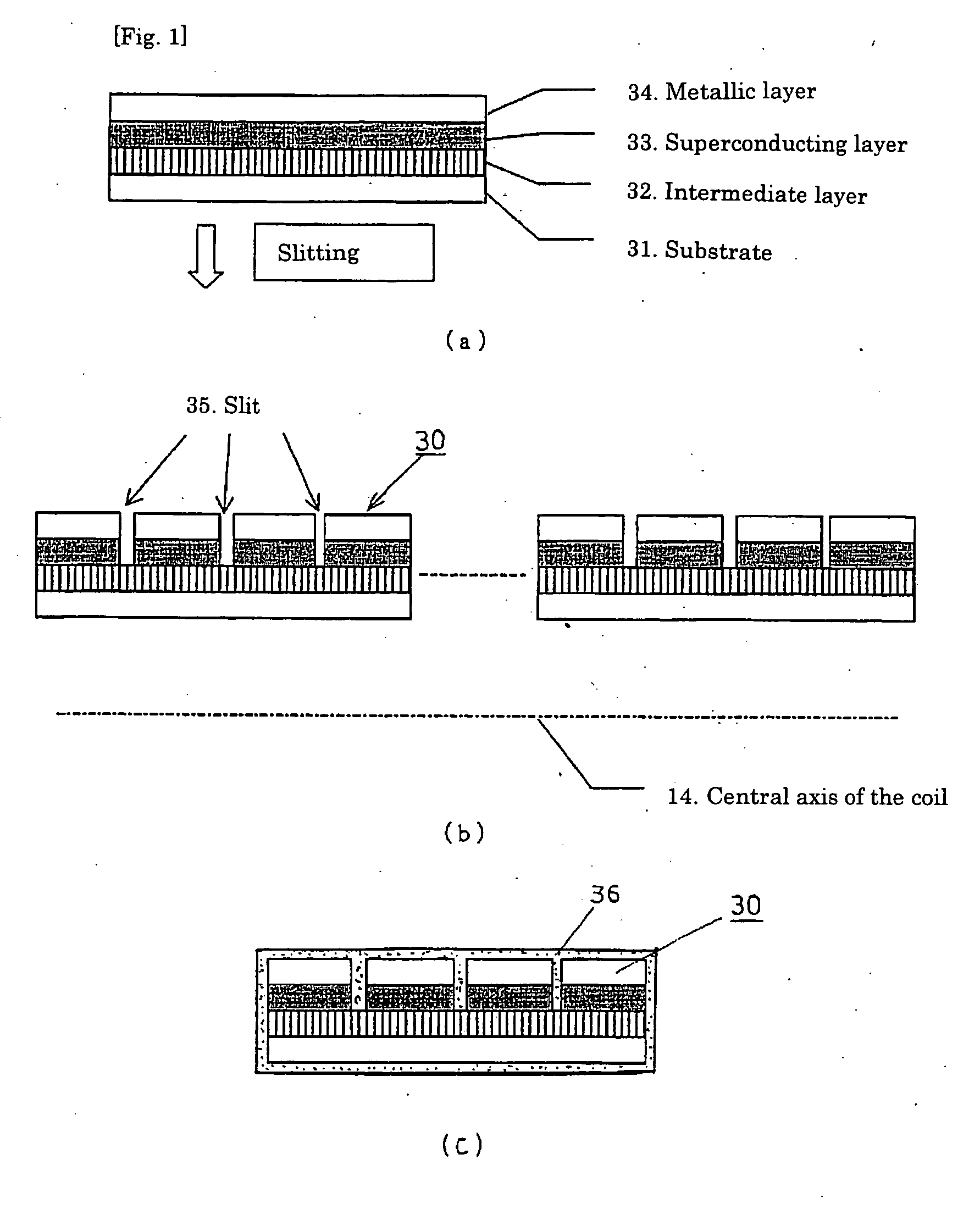
[0063]FIG. 1 is a typical cross-sectional view of superconducting wire showing an embodiment of the present invention and shows the structure of parallel conductors of which the superconducting film is split into four parts. FIG. 1(a) shows the superconducting conductor before its split, FIG. 1(b) shows the parallel conductor after the split by slitting. And FIG. 1(c) shows the parallel conductors after a coating for insulation.

[0064] In FIG. 1, 31 represents the substrate, 32 represents the intermediate layer, 33 represents the superconducting layer, 34 represents the metallic layer, 35 represents slits as splitting grooves, and 36 represents electrical insulating material. On the other han...


PUM


Abstract

Tape-shaped superconducting wires are made by forming a superconducting film on the substrate. At least the superconducting film is slit, electrically separated into a plurality of superconducting film parts each having a rectangular cross section and arranged in parallel to form parallel conductors. This provides superconducting wires capable of containing AC loss. A superconducting coil is made by winding the superconducting wires described above, wherein the provision of a coil structure containing at least partially a part wherein the perpendicular interlinkage magnetic flux acting among various conductor elements of the parallel conductors by the distribution of the magnetic field generated by the superconducting coils cancel mutually enables a simple structure without transposition to cancel mutually the interlinkage magnetic flux by the perpendicular magnetic field against wires, to contain circulating current within the wires by the perpendicular magnetic field and to make shunt current uniform. This provides a low-loss superconducting coil.

Description

TECHNICAL FIELD [0001] The present invention relates to a superconducting wire and a superconducting coil made therewith used in electric machinery and apparatuses in which current changes rapidly, for example storage of energy, magnetic field application, electric transformers, reactors, motors, electric generators and the like. BACKGROUND ART [0002] The superconducting coil has been put to practical use in various fields as a means of generating high magnetic fields. On the other hand, the practical application of superconducting coils to A.C. devices such as transformers and reactors has witnessed little progress due to the phenomenon of losses incurred by superconducting conductors in the presence of AC. [0003] However, since the recent development of a superconducting conductor having a small loss of AC by the thinning of superconducting stranded wires, a progress has been made in the researches for its application to transformers and other A.C. devices, and various proposals h...

Claims


Application Information

Patent Timeline
IPC IPC(8): H01F6/00H01F6/02H01F6/06H01F27/28H01F27/34
CPCH01F6/02H01F6/06H01F27/2852H01F27/2871H01F27/346H01L39/143Y10S505/704Y10S505/879Y10S505/887Y10S505/884Y10S505/705H10N60/203
Inventor FUNAKI, KAZUOIWAKUMA, MASATAKAKISU, TAKANOBUTOMIOKA, AKIRAUEDE, TOSHIOFUJI, HIROSHIIZUMI, TERUOSHIOHARA, YUH
Owner KISU TAKANOBU
Why Eureka
Try Eureka