

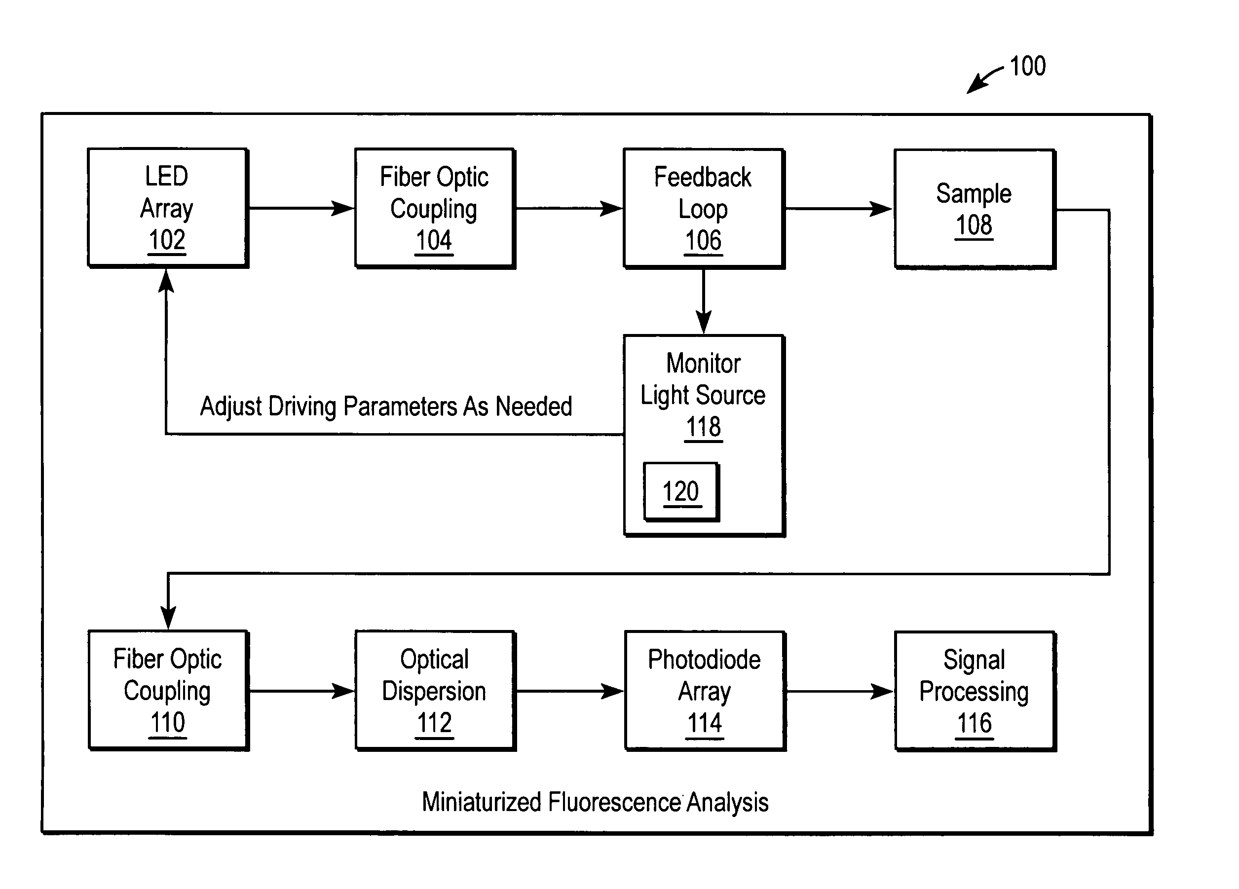
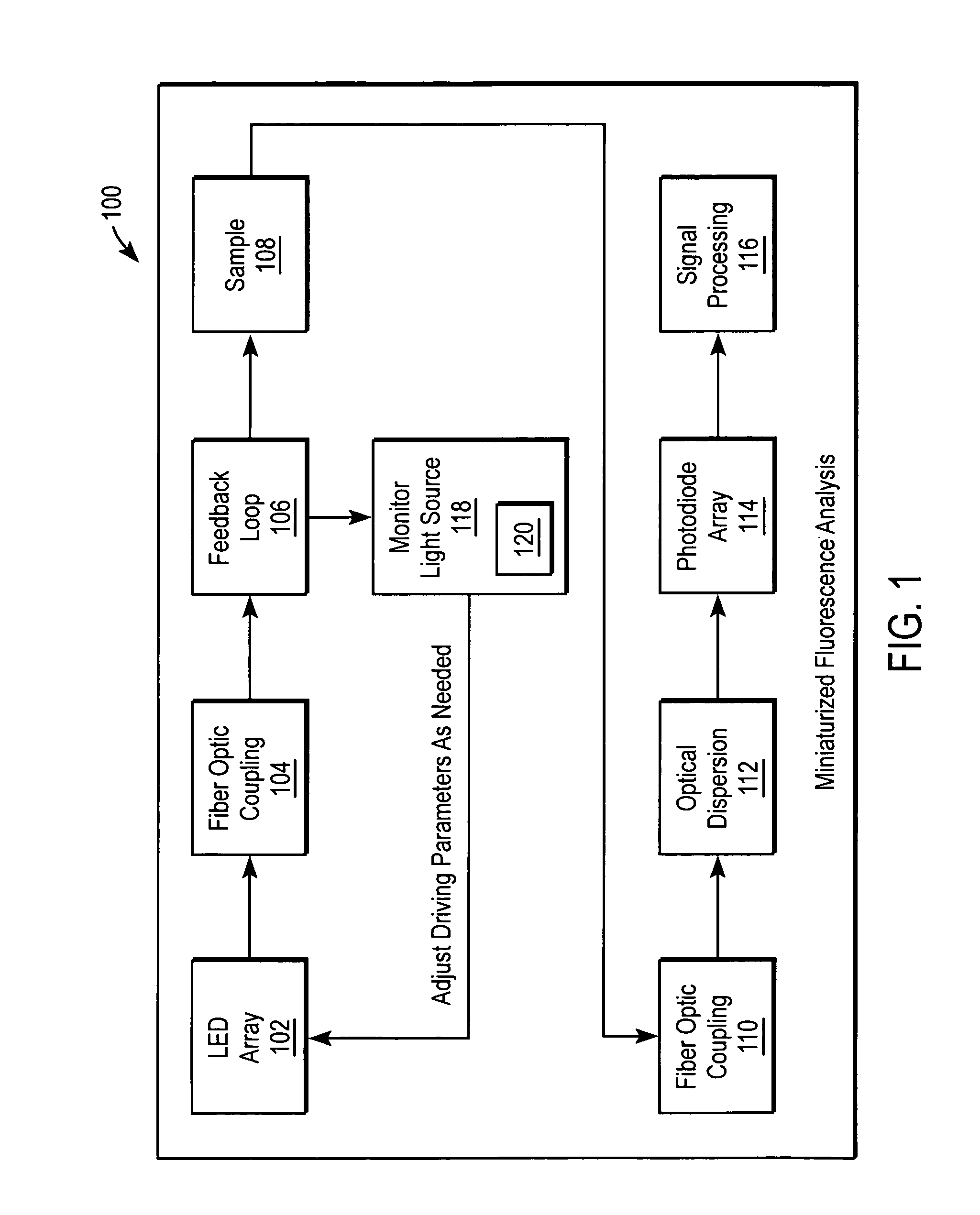
Miniaturized fluorescence analysis system
a fluorescence analysis and micro-fluorescence technology, applied in the field of fluorescence analysis systems, can solve the problems of not restricting effective sample measurements, limited use of leds, and insufficient matching of excitation peaks of leds to the absorption efficiency of fluorophors under analysis, so as to increase the flexibility and intensity of spectra and maximize the effect of emission signal collection
- Summary
- Abstract
- Description
- Claims
- Application Information
AI Technical Summary
Benefits of technology
Problems solved by technology
Method used
Image

Examples
Embodiment Construction
[0012] Embodiments of the present invention are directed to automated and modular optimization of fluorescence analysis system that may maximize signal extraction (SNR) from an excited fluorophor. In one embodiment, the system includes an array of light emitting diodes (LEDs) that emit excitation light. The excitation light may have a first color and / or wavelength (blue, blue-green, green, purple, or other suitable color / wavelength. The color and / or wavelength of the excitation light of one LED may be different than the color and / or wavelength of another excitation light of one LED.
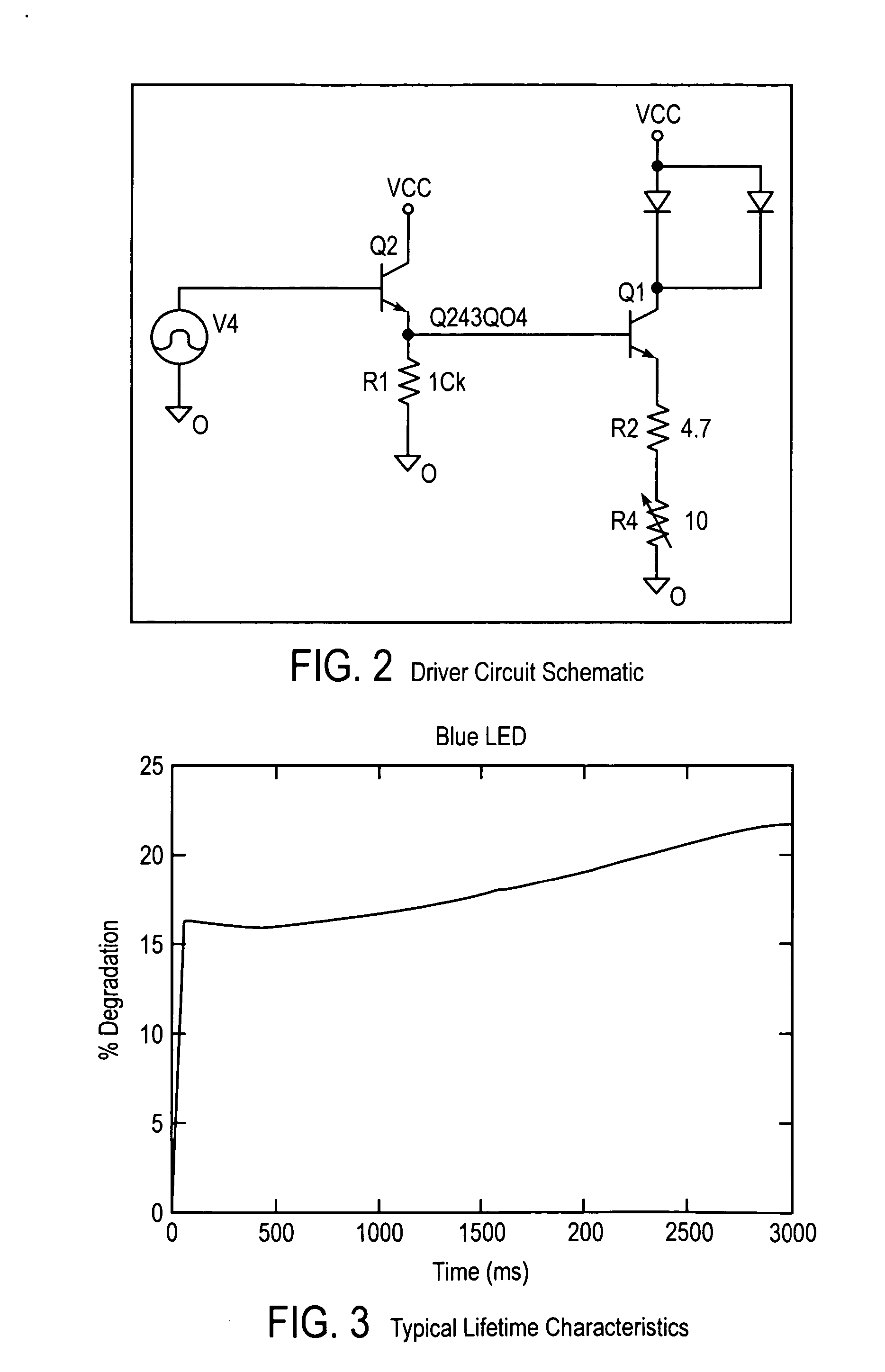
[0013] The system also includes control electronics that apply drive currents to the LEDs. The drive currents cause the LEDs to emit the excitation light. The drive current to one LED may be different than the drive current to another LED. For some embodiments, the drive current is greater than nominal drive current, greater than rated maximum current for the LED, and in may range between twenty and two...
PUM
 Abstract
Description
Claims
Application Information