Optical image measuring apparatus

a technology of optical image and measuring apparatus, which is applied in the field of optical image measuring apparatus, can solve the problems of prolonged measurement time and difficult shortening of measurement time in view of measurement fundamentals, and achieve the effect of efficient shortening of measurement tim

Inactive Publication Date: 2006-04-20
KK TOPCON
View PDF4 Cites 27 Cited by
  • Summary
  • Abstract
  • Description
  • Claims
  • Application Information

AI Technical Summary

Benefits of technology

[0072] signal processing means for forming an image reflecting a birefringent property, of the object to be measured based on the intensity change information of each of the polarized light components included in the outputted detection signal. Therefore, even when the image reflecting the birefringent property,

Problems solved by technology

Therefore, the measurement of the object to be measured 305 is needed to be carried out in a wide range for instance by scanning the signal light and requires a long

Method used


Image

  • Optical image measuring apparatus
  • Optical image measuring apparatus
  • Optical image measuring apparatus

Examples


first embodiment

[Structure of Apparatus]

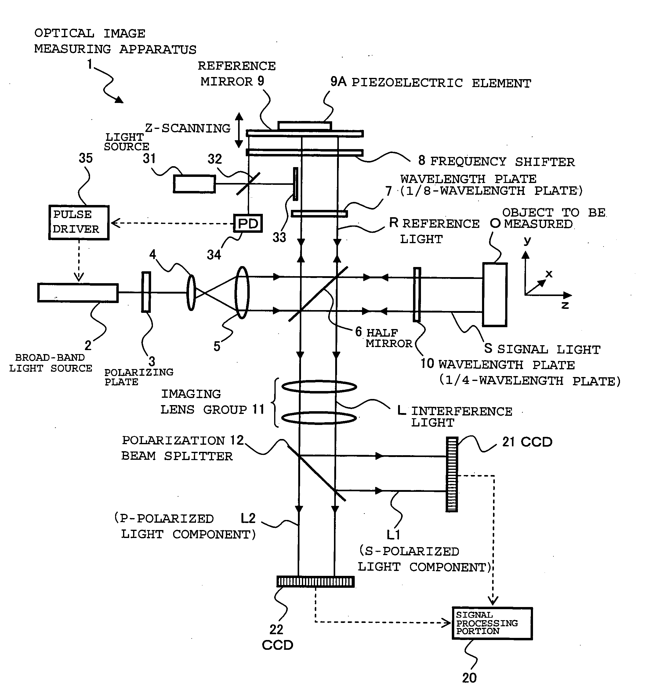
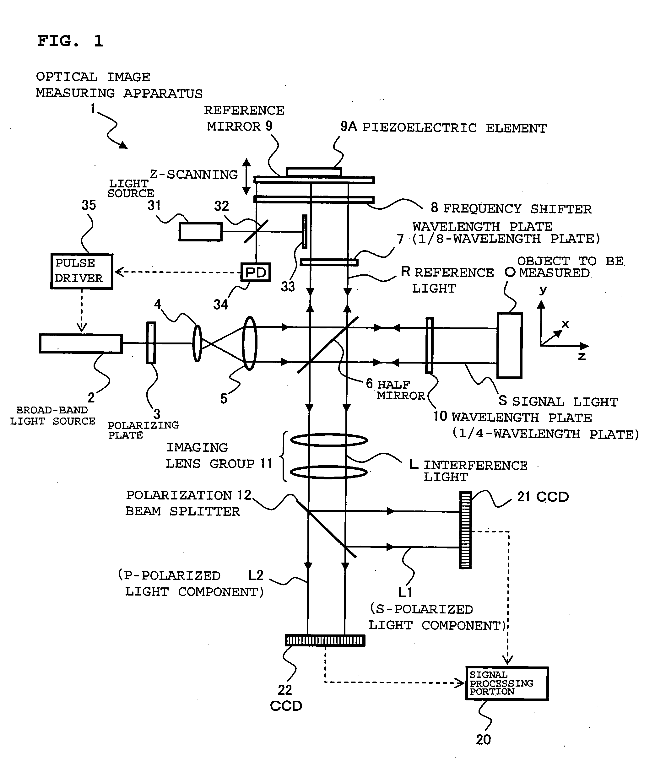
[0083]FIG. 1 is a schematic structural diagram showing an optical image measuring apparatus according to a first embodiment of the present invention. An optical image measuring apparatus 1 shown in FIG. 1 is an apparatus available to measure a tomographic image and a surface image of an object to be measured O which is made of a scattering medium in the medical field and the industrial field etc., in particular, to measure the tomographic image and the surface image of the object to be measured O which includes a layer having a birefringent property (birefringent layer), such as a retinal nerve fibre layer.

[0084] The optical image measuring apparatus 1 includes a broad-band light source 2 for outputting a low-coherent light beam, a polarizing plate 3 for converting a polarization characteristic of the light beam to linear polarization, lenses 4 and 5 for converting the light beam to a parallel light beam and increasing a beam diameter thereof, and a half mi...

second embodiment

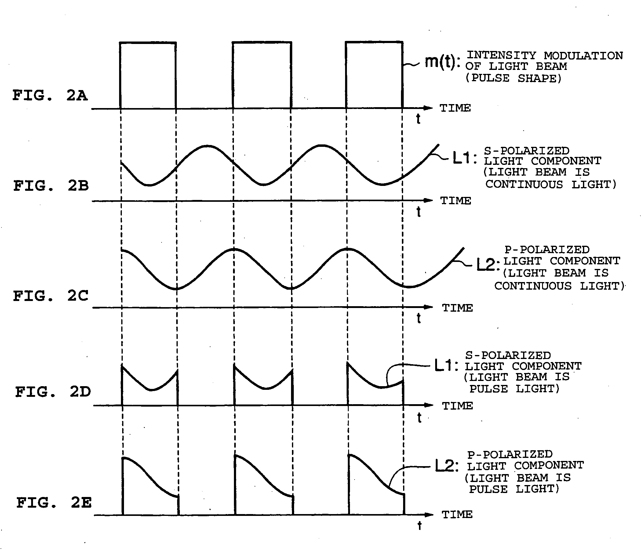
[0156] Subsequently, an optical image measuring apparatus according to a second embodiment of the present invention will be described. In this embodiment, interference light beams produced based on a continuously outputted light beam instead of the light beam whose intensity is modulated as in the first embodiment are sampled using shutters.

[0157] First, the optical image measuring apparatus according to this embodiment will be described. FIG. 4 illustrates a structural example of (mainly) an optical system of the optical image measuring apparatus according to this embodiment. In FIG. 4, the same reference symbols are provided to the same constituent portions as those in the first embodiment. Hereinafter, the detailed descriptions related to the same constituent portions as those in the first embodiment are omitted.

[0158] As in the first embodiment, an optical image measuring apparatus 100 shown in FIG. 4 includes the broad-band light source 2, the polarizing plate 3, the lenses 4...

modified example

[0166] In the above-mentioned optical image measuring apparatus 100, the shutters 41 and 42 are controlled so as to “simultaneously” cut off the S-polarized light component L1 and the P-polarized light component L2 at the frequency synchronized with the beat frequency of the interference light L in response to the pulse signals outputted from the pulse signal generator 50 based on the electrical signal from the photodetector 34. In the modified example described below, the S-polarized light component L1 and the P-polarized light component L2 are sampled by “changing open-and-close timings” of the shutters 41 and 42.

[0167]FIG. 5 illustrates an example showing a structure of an optical image measuring apparatus according to this modified example. An optical image measuring apparatus 100′ shown in FIG. 5 has a structure similar to that of the optical image measuring apparatus 100 according to the second embodiment.

[0168] In order to control the operations of the shutters 41 and 42, t...


PUM


Abstract

An optical image measuring apparatus capable of measuring an object to be measured which includes a birefringent layer in a short time is provided. The optical image measuring apparatus includes a broad-band light source, lenses for increasing a diameter of the light beam, a polarizing plate, a half mirror, a wavelength plate for converting the reference light to circularly polarized light, a wavelength plate for converting the signal light to circularly polarized light and converting the signal light to linearly polarized light, a frequency shifter, a polarization beam splitter for separating an S-polarized light component and a P-polarized light component from interference light, CCDs for receiving the respective polarized light components and outputting detection signals each including intensity change information, and a signal processing portion for forming an image reflecting a birefringent property, of an object to be measured based on the intensity change information.

Description

BACKGROUND OF THE INVENTION [0001] 1. Field of the Invention [0002] The present invention relates to an optical image measuring apparatus that applies a light beam to an object to be measured, particularly a light scattering medium, and produces a surface form or inner form of the object to be measured by detecting a reflected light beam or a transmitted light beam. In particular, the present invention relates to an optical image measuring apparatus for measuring the surface form or inner form of the object to be measured by using an optical heterodyne detection method to produce the image of the measured form. [0003] 2. Description of the Related Art [0004] In recent years, attention has been given to optical imaging technique that produces an image of a surface or inner portion of an object to be measured using a laser light source or the like. This optical imaging technique is not hazardous to human bodies in contrast to the conventional X-ray CT. Therefore, the development of ap...

Claims


Application Information

Patent Timeline
IPC IPC(8): G01B9/02
CPCA61B3/1225A61B5/0073G01B11/2441G01B9/02003G01B9/02027G01B9/02091G01B9/02014G01B9/02069G01B2290/70G01B2290/45A61B5/4041
Inventor CHAN, KINPUIAKIBA, MASAHIRO
Owner KK TOPCON
Why Eureka
Try Eureka