Resonator
- Summary
- Abstract
- Description
- Claims
- Application Information
AI Technical Summary
Benefits of technology
Problems solved by technology
Method used
Image

Examples
first embodiment
Embodiment 1
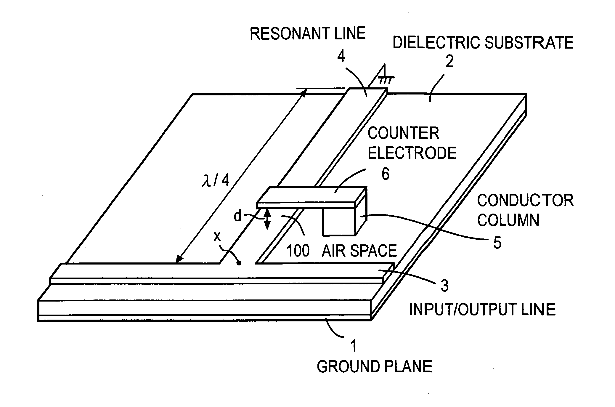
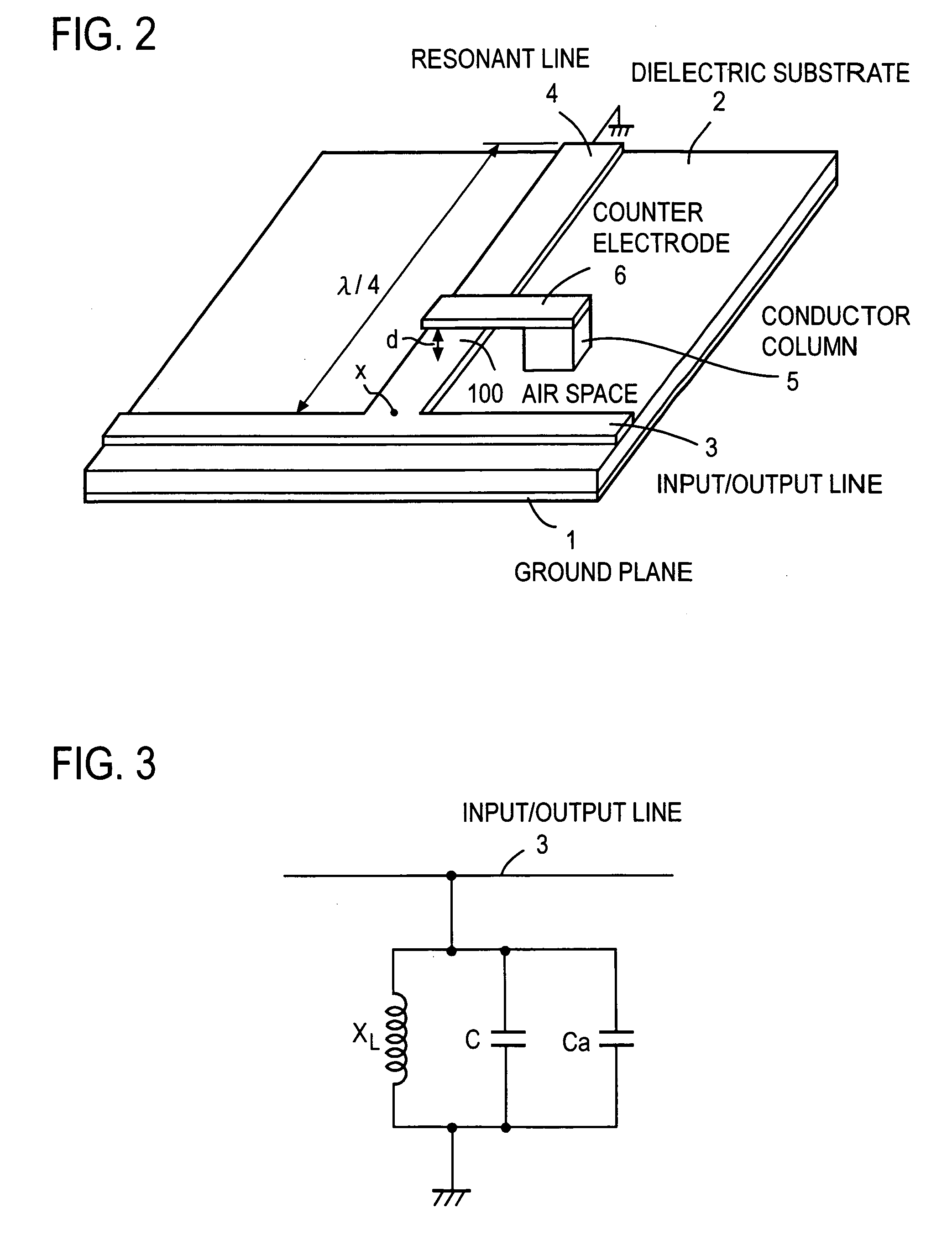
[0052]FIG. 2 shows a resonator of the present invention using a microstrip line. An input / output line 3 is formed on the surface of a dielectric substrate 2, on which reverse side a ground plane 1 is formed. A high frequency signal is inputted from one end of the input / output line 3. A resonant line 4 having a length of about a quarter of the wavelength λ of the resonant frequency f is connected to nearly a center part of the input / output line 3, and formed on the dielectric substrate 2 in the direction perpendicular to the input / output line 3. The end of the resonant line 4 is electrically connected to the grounded ground plane 1. A counter electrode 6 facing a partial area of the resonant line 4 with an air gap 100 of a distance d in the direction perpendicular to the resonant line 4 is arranged. The counter electrode 6 is supported by a conductor column 5, and the conductor column 5 is connected to the ground plane 1 by a not shown Via hole (a conductor electrically ...
embodiment 2
[0059]FIG. 6 shows an embodiment of the present invention, in which a further miniaturization is effected by increasing and decreasing the width of the resonance line in the lengthwise direction of the resonance line, that is, by forming recessions and projections at the side edges of the resonance line. The parts corresponding to those explained with reference to FIG. 2 are denoted by the same reference numbers, and the explanation of these parts is omitted. The shape of a resonant line 7 is different from that in FIG. 2. A high frequency signal is inputted from one end of the input / output line 3. The resonance line 7 having a same width W1 as the input / output line 3 and a length L1 is arranged approximately from the middle part of the input / output line 3 in the direction perpendicular to the input / output line 3. Both sides of a part with a length T extended from a position at a distance of L1 from the input / output line 3, are provided with widened parts 7a, 7b in parallel with the...
embodiment 3
[0069]FIG. 8 shows an embodiment of a quarter wavelength line resonator with the tip short-circuited, in the case where the standing wave effect is taken into consideration. In the present embodiment, components already explained are denoted by the same reference numerals, and the explanation of the components is omitted. Widened parts 9a, 9b are arranged with a same pitch Lp at both side edges of a main resonant line 8 extended perpendicularly to the input / output line 3. For example, the pitch Lp is set to λ / 128, that is, the length of each of the widened parts 9a, 9b in the direction parallel to the input / output line 3 is set to λ / 128. In addition, the length of each of the widened parts 9a, 9b in the direction perpendicular to the input / output line 3 is also set to λ / 128. The widened parts 9a, 9b are repeatedly provided up to the position at a distance of λ / 8 from the input / output line 3. That is, four widened parts are arranged. The pitch Lp may not necessarily be the same, and ...
PUM
 Abstract
Description
Claims
Application Information
 - Generate Ideas
- Intellectual Property
- Life Sciences
- Materials
- Tech Scout
- Unparalleled Data Quality
- Higher Quality Content
- 60% Fewer Hallucinations
Browse by: Latest US Patents, China's latest patents, Technical Efficacy Thesaurus, Application Domain, Technology Topic, Popular Technical Reports.
© 2025 PatSnap. All rights reserved.Legal|Privacy policy|Modern Slavery Act Transparency Statement|Sitemap|About US| Contact US: help@patsnap.com