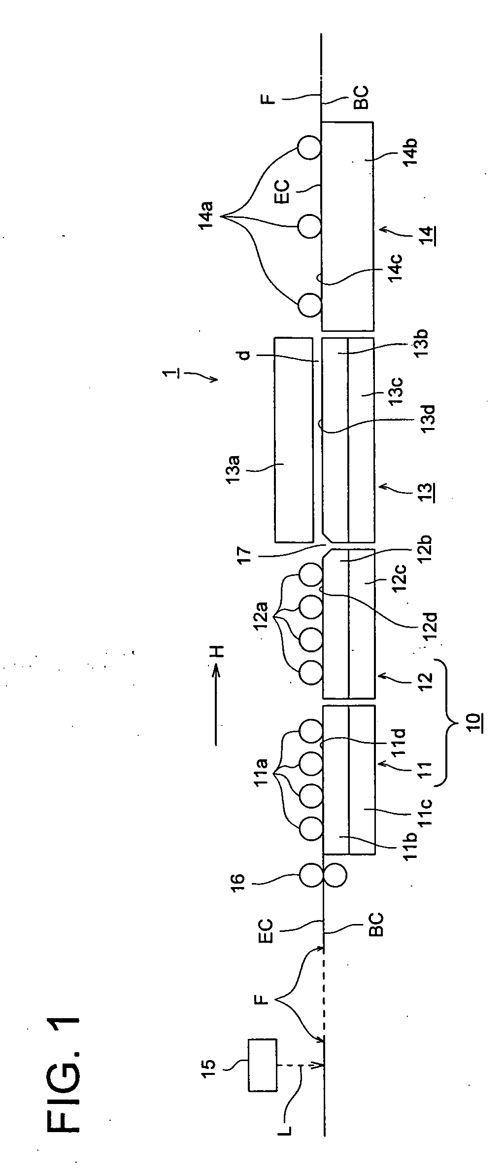
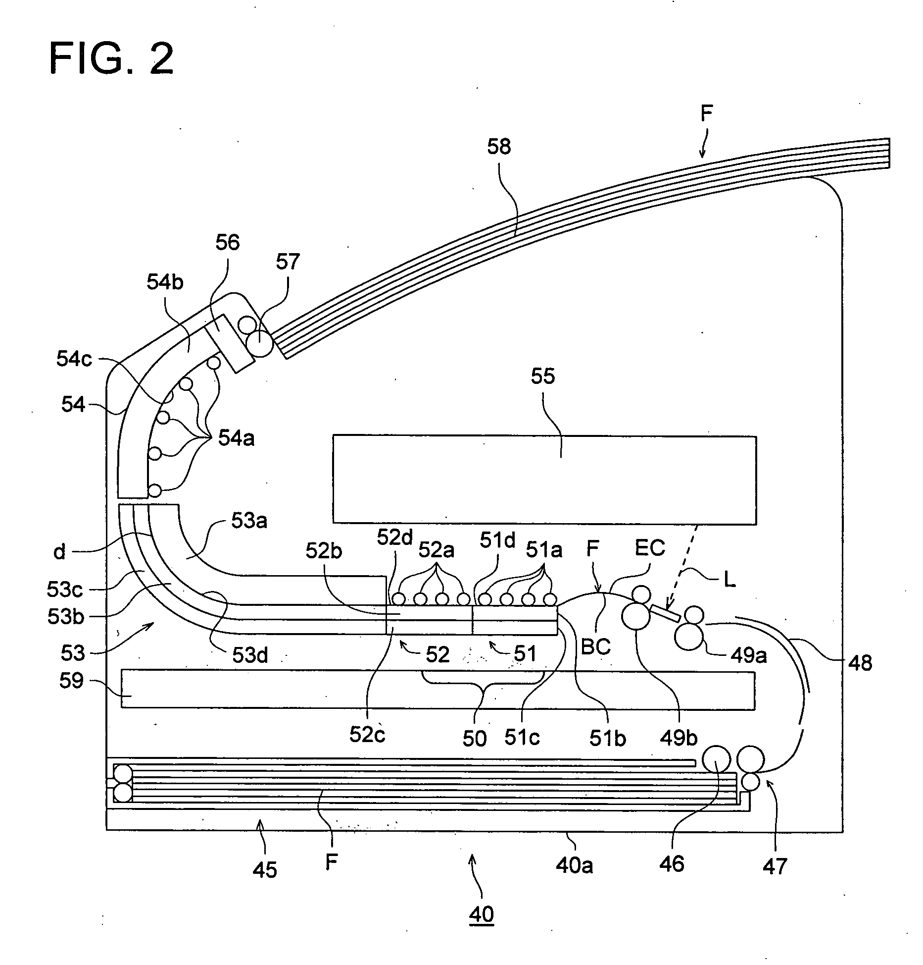
Silver salt photothermographic dry imaging material, thermal development method of the same, and thermal development apparatus for the same

Inactive Publication Date: 2006-04-27
KONICA MINOLTA MEDICAL & GRAPHICS INC
View PDF41 Cites 3 Cited by
  • Summary
  • Abstract
  • Description
  • Claims
  • Application Information

AI Technical Summary

Benefits of technology

[0022] This invention has been made in view of the above-described background, and an object is to provide a silver salt photothermographic dry imaging material, a thermal development method and a thermal development apparatus thereo

Problems solved by technology

Heretofore, in the medical and printing plate making fields, effluent resulting from wet type processing for image forming materials became problematic in terms of workability, and in recent years, from the viewpoint of environmental protection as well as space saving, a decrease in processing effluent has been highly demanded.
Further, in a photothermographic dry imaging material utilizing photosensitive silver halide grains, there is a problem of deterioration of light irradiation image lasting quality (storage stability when an image obtained by thermal development is used in a daylight room for such as diagnosis or stored in a daylight room) b

Method used


Image

  • Silver salt photothermographic dry imaging material, thermal development method of the same, and thermal development apparatus for the same
  • Silver salt photothermographic dry imaging material, thermal development method of the same, and thermal development apparatus for the same
  • Silver salt photothermographic dry imaging material, thermal development method of the same, and thermal development apparatus for the same

Examples


Example

SYNTHETIC EXAMPLE 1

Synthesis of P-1

[0232] Charged into a reaction vessel were 20 g of polyvinyl alcohol (Gosenol GH18) manufactured by Nihon Gosei Co., Ltd. and 180 g of pure water, and the resulting mixture-was dispersed in pure water so that 10 weight percent polyvinyl alcohol dispersion was obtained. Subsequently, the resultant dispersion was heated to 95° C. and polyvinyl alcohol was dissolved. Thereafter, the resultant solution was cooled to 75° C., whereby an aqueous polyvinyl alcohol solution was prepared. Subsequently, 1.6 g of 10 percent by weight hydrochloric acid, as an acid catalyst, was added to the solution. The resultant solution was designated as Dripping Solution A. Subsequently, 11.5 g of a mixture consisting of butylaldehyde and acetaldehyde in a mol ratio of 4:5 was prepared and was designated as Dripping Solution B. Added to a 1,000 ml four-necked flask fitted with a cooling pipe and a stirring device was 100 ml of pure water which was heated to 85° C. and sti...

Example

EXAMPLE

[0679] This invention will now be detailed with reference to examples. However, this invention is not limited to these examples. “Percent (or %)” in the examples is “% by weight (or wt %)”, if not otherwise specified.

Example 1

>

[0680] A photographic support comprised of a 175 μm thick biaxially oriented polyethylene terephthalate film with blue tinted at an optical density of 0.170 (determined by Densitometer PDA-65, manufactured by Konica Corp.), which had been subjected to corona discharge treatment of 8 W·minute / m2 on both sides, was subjected to subbing. Namely, subbing liquid coating composition a-1 was applied onto one side of the above photographic support at 22° C. and 100 m / minute to result in a dried layer thickness of 0.2 μm and dried at 140° C., whereby a subbing layer on the image forming layer side (designated as Subbing Layer A-1) was formed. Further, subbing liquid coating composition b-1 described below was applied, as a backing layer subbing layer, onto th...

Example

Example 2

[0735] Under coating was performed on a photographic support in which the both surfaces of polyethylene terephthalate film, having been colored with the following blue dye, biaxially stretched and thermally fixed, and having a thickness of 175 μm, had been subjected to a corona discharge treatment of 8 W·min / m2. That is, under-coat layer coating composition a-1 was coated at 22° C., 100 m / min, on the one surface of the photographic support so as to make a dry thickness of 0.2 μm, followed by being dried at 140° C. to form a photosensitive layer (an image forming layer) side under-coat layer (referred to as under-coat layer A-2). Further, under-coat layer coating composition b-1 was coated at 22° C., 100 m / min, as a backing layer side under-coat layer, on the opposite surface so as to make a dry thickness of 0.2 μm, followed by being dried at 140° C. to form a under-coat conductive layer (referred to as under-coat layer B-2) provided with a antistatic function on a backing ...


PUM


Abstract

A photothermographic imaging material comprising a support having thereon, (a) a photosensitive layer containing an organic silver salt, photosensitive silver halide grains, a reducing agent and a binder, (b) a light-insensitive layer, and (c) a protective layer, wherein a weight reducing value from 25° C. to 100° C. by a heat drying weight measurement of the photographic imaging material is not more than 0.4% based on a weight value at 25° C.

Description

[0001] This application is based on Japanese Patent Application Nos. 2004-307905 filed on Oct. 22, 2004, 2005-083351 filed on Mar. 23, 2005. FIELD OF THE INVENTION [0002] The present invention relates to a silver salt photothermographic dry imaging material, a thermal developing method of the photothermographic material, and a thermal developing apparatus for the same. BACKGROUND OF THE INVENTION [0003] Heretofore, in the medical and printing plate making fields, effluent resulting from wet type processing for image forming materials became problematic in terms of workability, and in recent years, from the viewpoint of environmental protection as well as space saving, a decrease in processing effluent has been highly demanded. Accordingly, a silver salt photothermographic dry imaging material, which can perform image formation only by heating, has been brought into practical use and rapidly prevailing in the above fields. [0004] A photothermographic dry imaging material itself has b...

Claims


Application Information

Patent Timeline
IPC IPC(8): G03C1/76
CPCG03C1/061G03C1/498G03C1/49818G03C1/49845G03C1/49863G03C1/49881G03C1/04G03C2200/58G03C2200/60G03C1/08G03C1/485G03C2001/03564G03C2001/03594G03C2200/09G03C2200/43G03C2200/52
Inventor KUWANO, KOJISASAKI, TAKAYUKIKIDO, KAZUHIRO
Owner KONICA MINOLTA MEDICAL & GRAPHICS INC
Why Eureka
Try Eureka