
Gas-introducing system and plasma CVD apparatus

a plasma cvd and gas-introducing system technology, applied in the direction of chemical vapor deposition coating, coating, electric discharge tube, etc., can solve the problems of thermal energy generation, micro-cracks at the surface of the blocker plate, and the remote plasma cleaning method also gave rise to a new set of problems, so as to effectively prevent the cleaning speed from dropping, eliminate ion bombardment, and high cleaning speed

Active Publication Date: 2006-05-04
ASM JAPAN
View PDF14 Cites 154 Cited by
  • Summary
  • Abstract
  • Description
  • Claims
  • Application Information

AI Technical Summary

Benefits of technology

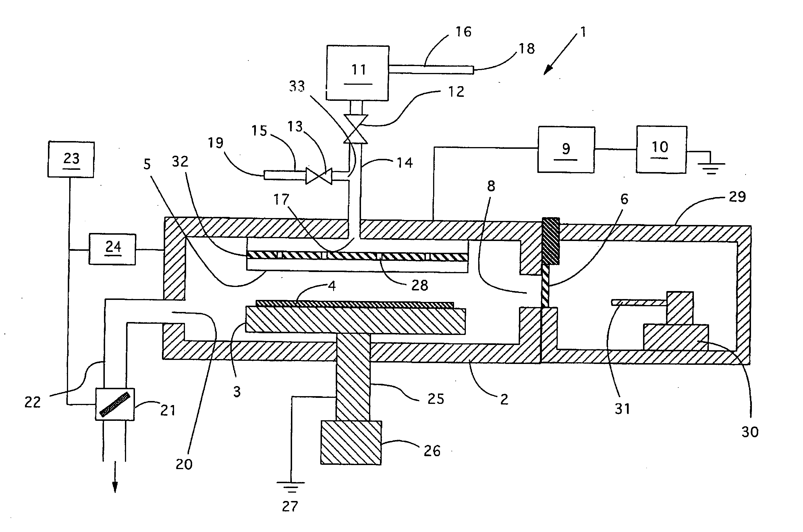
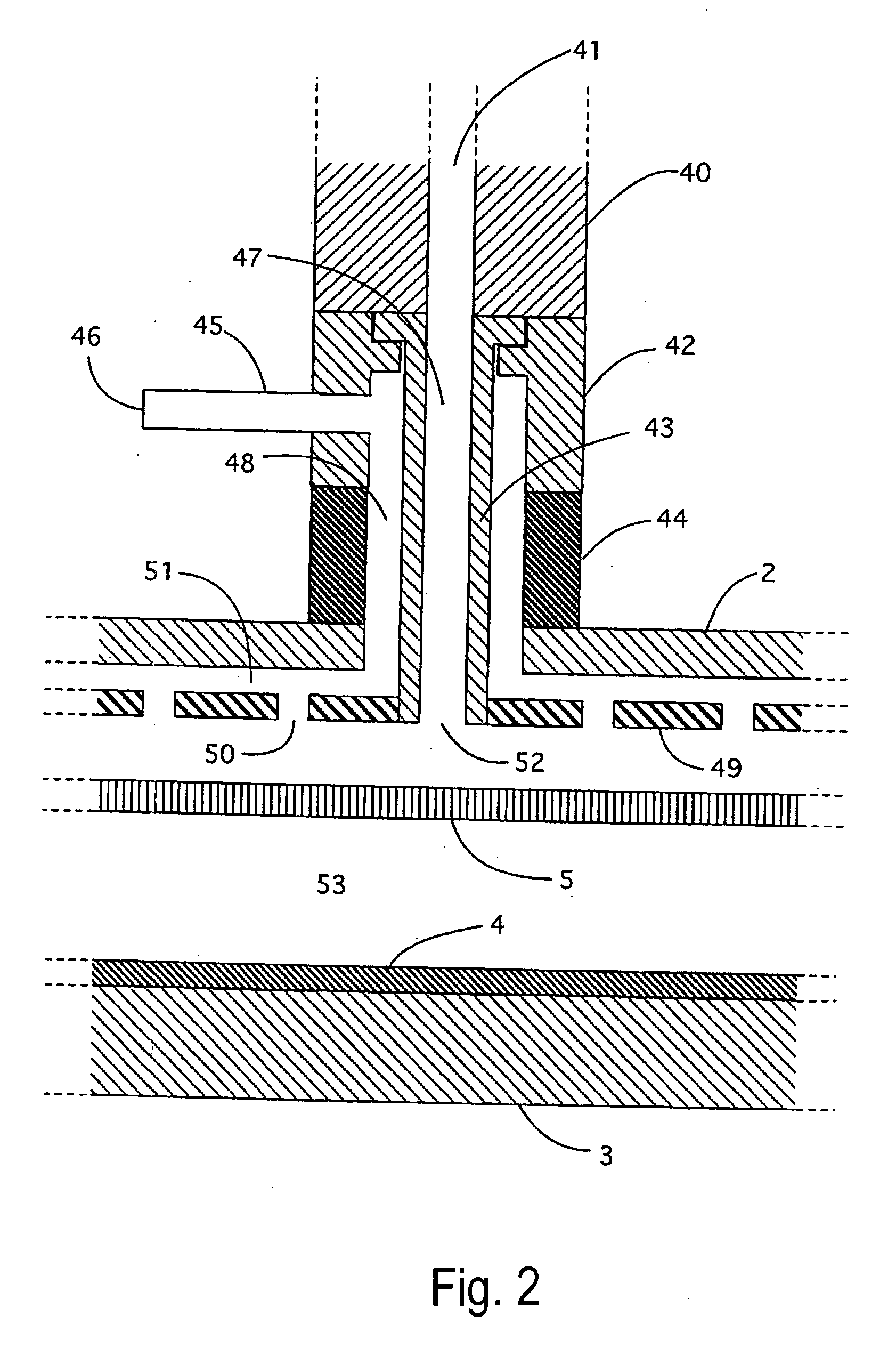
[0012] The inventor discovered that even when the blocker plate is made of conventional alumina ceramics, the rate of this inactivation becomes high and the cleaning speed consequently drops by approx. 25% as compared with the initial cleaning speed. This may be because the blocker plate made of conventional alumina ceramics has a porous surface structure and can be explained as follows, although any theories described herein are not intended to limit all embodiments of the present invention. When active fluorine species collide with the blocker plate, thermal energy generates and causes micro-cracks at the surface of the blocker plate. These micro-cracks cause fine particles to separate, which then attach to the surfaces of the blocker plate and showerhead. These attached fine particles mainly comprising aluminum oxide or aluminum fluoride increase the surface area of the blocker plate and thereby promote the inactivation of cleaning gas containing active fluorine species.
[0014] Consequently, the invention provided in the present patent application was developed to address the aforementioned problems. Specifically, in an embodiment, an object of the present invention is to provide a plasma CVD apparatus having a remote plasma discharge chamber that can eliminate ion bombardments and thereby inhibit the cleaning speed from dropping.
[0027] In at least one or more of the above aspects and embodiments, the present invention realizes a plasma CVD apparatus that can eliminate ion bombardments while maintaining a high cleaning speed for a long period by effectively preventing the cleaning speed from dropping.
[0028] Also, in at least one or more of the above aspects and embodiments, the present invention also realizes a plasma CVD apparatus that achieves uniform film deposition and high cleaning speed at the same time.
[0029] Furthermore, in at least one or more of the above aspects and embodiments, the present invention can significantly reduce the time and cost required for maintaining the apparatus, thereby improving the productivity of the apparatus.

Problems solved by technology

While improving the problem of ion bombardments, the remote plasma cleaning method also gave rise to a new set of problems as explained below.
When active fluorine species collide with the blocker plate, thermal energy generates and causes micro-cracks at the surface of the blocker plate.
These micro-cracks cause fine particles to separate, which then attach to the surfaces of the blocker plate and showerhead.
Accordingly, such drop in cleaning speed is difficult to detect during the operation of the apparatus.
If the cleaning speed drops, the interior of the reactor cannot be sufficiently cleaned within the specified cleaning time, in which case residual material will attach to the wafers processed after the cleaning and cause wafer contamination.
If the apparatus is used for long hours, the cleaning speed drops gradually.
This maintenance must be performed with the apparatus stopped, which causes the productivity to drop significantly.

Method used


Image

  • Gas-introducing system and plasma CVD apparatus
  • Gas-introducing system and plasma CVD apparatus
  • Gas-introducing system and plasma CVD apparatus

Examples


examples

[0064] A comparative experiment on cleaning speed was conducted. The details of the experiment are explained below.

[0065] In the experiment, a process for depositing 500 m silicon oxide film on a silicon wafer, and a process for cleaning the reactor, were implemented repeatedly for a total of 40,000 silicon wafers under the gas and pressure conditions specified above, after which 500 nm film was deposited on one identical wafer, and then the cleaning sequence was implemented again to measure the cleaning speed. The results of this experiment are shown in Table 1. Here, “Conventional” represents a condition in which a general rectifying plate made of conventional alumina ceramics (a purity of 99.5% or higher, e.g., 99.7%) was used. “Example 1” represents a condition in which a sapphire rectifying plate conforming to the present invention was used. “Example 2” represents a condition in which a plasma CVD apparatus with a double pipe structure (and a rectifying plate made of alumina c...


PUM

PropertyMeasurementUnit
surface roughnessaaaaaaaaaa
thicknessaaaaaaaaaa
distanceaaaaaaaaaa

Abstract

A gas-introducing system for plasma CVD and cleaning includes: a showerhead including a top plate with a gas inlet port and a shower plate; a rectifying plate installed in the interior space of the showerhead and dividing the interior space into an upper space and a lower space; a structure for inhibiting inactivation of active species of the activated cleaning gas at the rectifying plate; and a piping unit for connecting the gas inlet port of the showerhead to a remote plasma unit and a reaction gas introduction port.

Description

BACKGROUND OF THE INVENTION [0001] 1. Field of the Invention [0002] The present invention generally relates to a semiconductor processing apparatus, and specifically to a plasma CVD apparatus having a self-cleaning device. [0003] 2. Description of the Related Art [0004] Traditionally, CVD apparatuses have been used to deposit insulation film made of silicon oxide, silicon nitride, amorphous carbon or polymers containing benzene rings, conductive film made of tungsten silicide, titanium nitride or aluminum alloy, or high dielectric constant film containing PZT (PbZr1−xTixO3), BST (BaxSr1−xTiO3) or the like, on silicon substrates or glass substrates. [0005] To deposit these films, reaction gas or secondary reaction gas, of various compositions, is supplied to the reactor. When plasma energy is applied, the reaction gas causes chemical reaction and forms a desired thin film on a semiconductor substrate. The film resulting from the reaction also attaches to the interior walls of the rea...

Claims


Application Information

Patent Timeline
Patent Type & Authority Applications(United States)
IPC IPC(8): C23C16/00C23F1/00
CPCC23C16/4405C23C16/45565C23C16/5096C23F4/00H01J37/32091H01J37/3244
Inventor SATOH, KIYOSHIFUKASAWA, YASUSHIMATSUMOTO, KAZUYA
Owner ASM JAPAN
Learn More