Covering of scintillation detector with a reflective coating

Inactive Publication Date: 2006-05-04
SCHLUMBERGER TECH CORP
View PDF11 Cites 18 Cited by
  • Summary
  • Abstract
  • Description
  • Claims
  • Application Information

AI Technical Summary

Benefits of technology

[0009] Preferably, the inner coating is thermally conductive. The thermal conductivity ensures a good heat transfer inside the crystal, so that the temperature on the coating layer and crystal int

Problems solved by technology

A problem associated with MWD applications is that the reflector used in the detector, specular or diffuse, will suffer from those high temperatures and high shocks.
When a diffuse reflector as a dry aluminum powder is used, after some shocks it will clog at one end of the crystal package and fail to reflect light at all surfaces.
And when a specular reflector as polytetrafluoroethene (PTFE) tape, or any type of foil is used, the inhomogeneities of the crystal edge do not ensure a perfect contact between the crystal and the foil.
Air and gas are irr

Method used


Image

  • Covering of scintillation detector with a reflective coating
  • Covering of scintillation detector with a reflective coating

Examples


Embodiment Construction

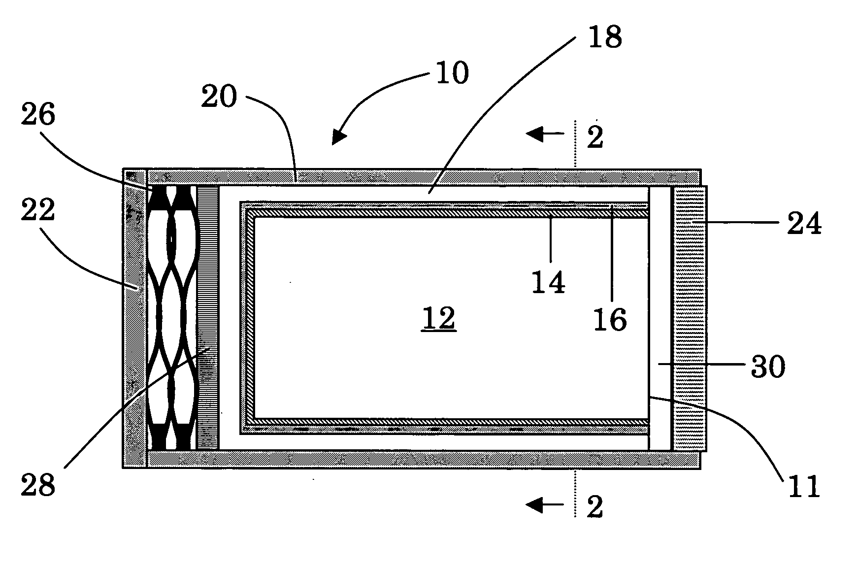
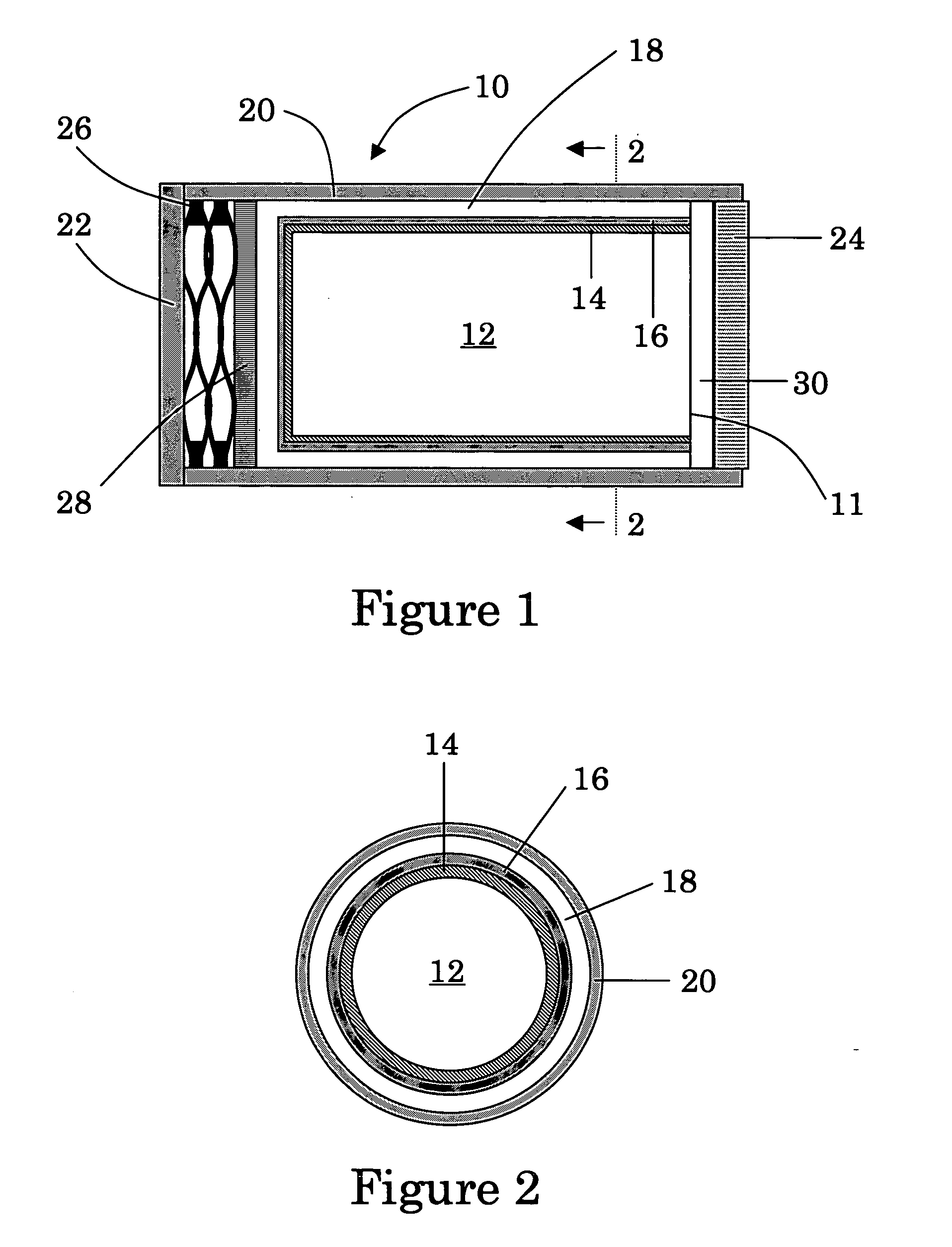
[0029]FIG. 1 is a view of a scintillation crystal package in accordance with the invention.

[0030]FIG. 2 is a cross-sectional view of the scintillation crystal package taken along the line 2-2 of FIG. 1.

[0031] Referring now in detail to the drawings, FIG. 1 and 2 illustrate an exemplary and preferred scintillation crystal package 10 according to the present invention. Package 10 comprises of a scintillation crystal 12, which is covered with an inner primary coating layer 14, this primary coating layer 14 covering all the surface of the crystal except the front-end face 11 of the crystal. In the illustrated preferred embodiment, the scintillation crystal 12 has the shape of a right cylinder. It is contemplated that the invention may have application to crystals of other shapes and the layers may be applied to a crystal surface other than a cylindrical surface. Scintillation crystal 12 is a sodium iodide crystal activated with thallium NaI(TI). NaI(TI) is an excellent light yield to p...


PUM


Abstract

The present invention discloses a scintillation detector 10 comprising a scintillation crystal 12 covered by an inner coating layer 14, said inner coating layer 14 being reflective to light spectrum, and said inner coating layer 14 being stuck directly to said crystal by a chemical and/or a physical binding. According to further aspect of the invention, a method is disclosed to measure radiation from an wellbore environment with the aforementioned scintillation detector 10. According to a still further aspect of the invention, a method is disclosed to manufacture a scintillation detector 10, comprising the steps of: defining two surface parts in a scintillation crystal 12: first and second part, covering said first part of said scintillation crystal 12 with an inner coating layer 14, said inner coating layer 14 being reflective to light spectrum and said inner coating layer 14 being stuck directly to said crystal 12 by a chemical and/or a physical binding, leaving said second part without coating, positioning said scintillation crystal 12 and said inner coating layer 14 in a shock absorbing member 18, positioning said second part in front of an optical window 24 transmissive to scintillation light given by said scintillation crystal 12, positioning said shock absorbing member 18 and said optical window 24 in a protective housing 20.

Description

FIELD OF THE INVENTION [0001] This present invention relates generally to a scintillation detector and method for performing radiation-based measurements, and to a method of manufacturing a scintillation detector. The scintillation detector and method are particularly useful for borehole logging applications. DESCRIPTION OF THE PRIOR ART [0002] Scintillation detectors have been employed in the oil and gas industry for well logging. These detectors have used thallium activated sodium iodide crystals that are effective in detecting gamma ray radiations. The crystals are enclosed in tubes or casings to form a crystal package. The crystal package has an optical window at one end of the casing, which permits scintillation light induced by radiation to pass out of the crystal package for measurement by a light sensing device such as a photomultiplier tube coupled to the crystal package. The photomultiplier tube converts the light photons emitted from the crystal into electrical pulses tha...

Claims


Application Information

Patent Timeline
IPC IPC(8): G01T1/20
CPCG01T1/2002G01T1/202
Inventor SAENGER, RICHARD
Owner SCHLUMBERGER TECH CORP
Why Eureka
Try Eureka