Multi bridge channel field effect transistors with nano-wire channels and methods of manufacturing the same

a field effect transistor and nano-wire technology, applied in the field of field effect transistors, can solve the problems of limiting the number of spaced channel layers that may be included, the inability to operate desirably at high speed of the semiconductor device including the conventional mos transistor having the mbc structure, and the limitation of the number of channel layers. , to achieve the effect of small cross-section

Active Publication Date: 2006-05-04
SAMSUNG ELECTRONICS CO LTD
View PDF3 Cites 123 Cited by
  • Summary
  • Abstract
  • Description
  • Claims
  • Application Information

AI Technical Summary

Benefits of technology

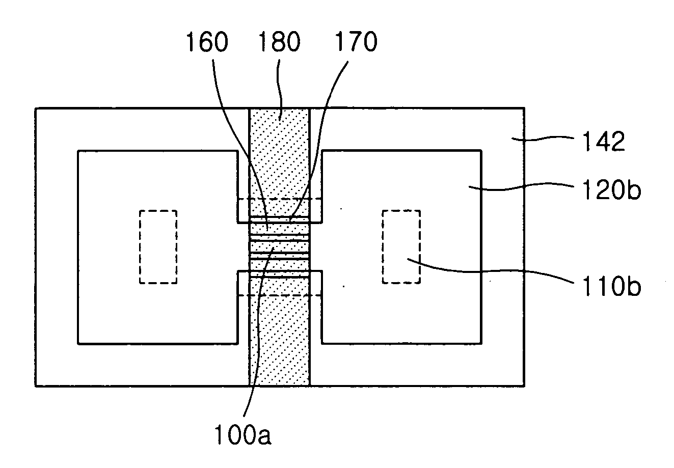
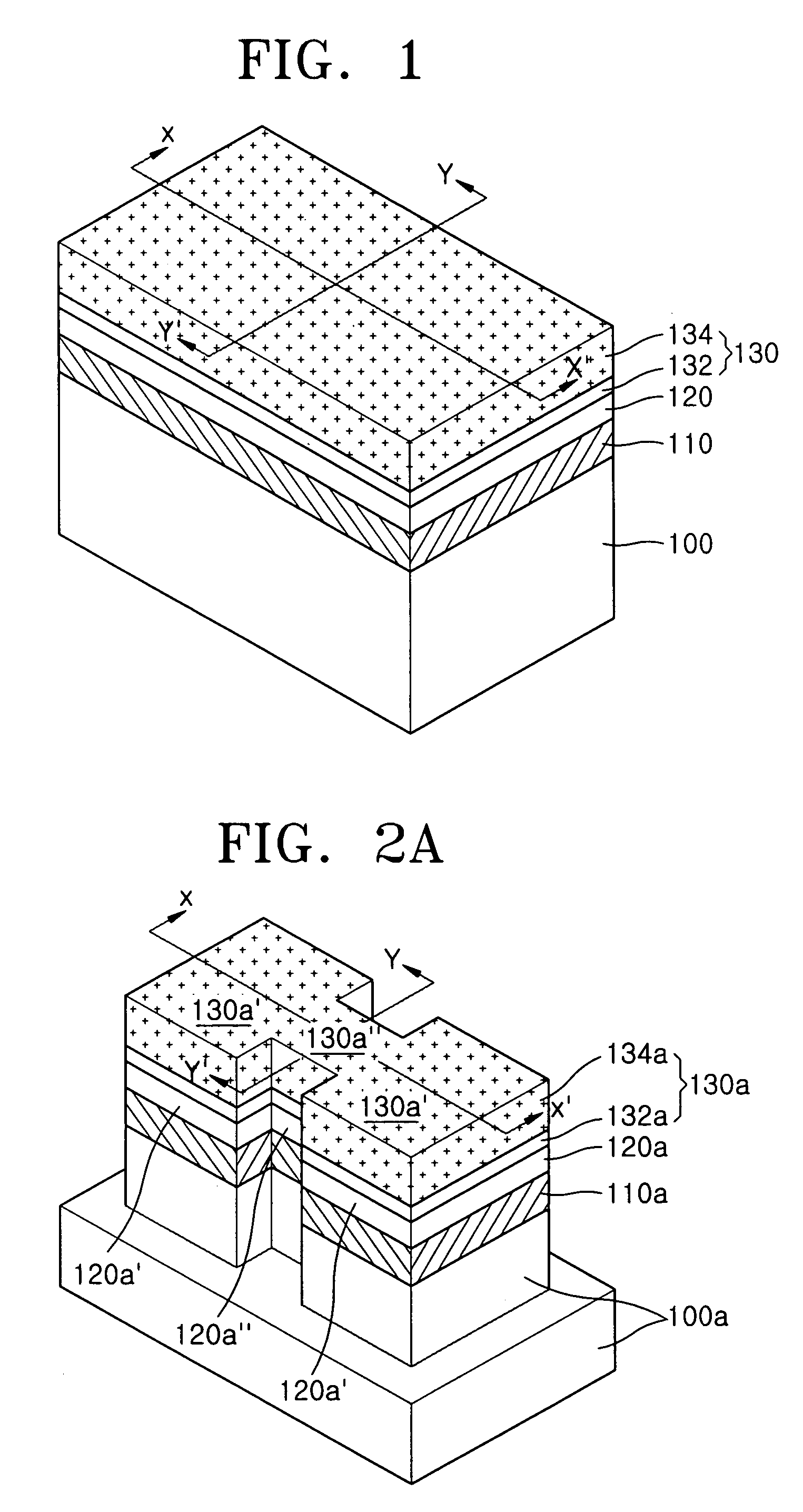
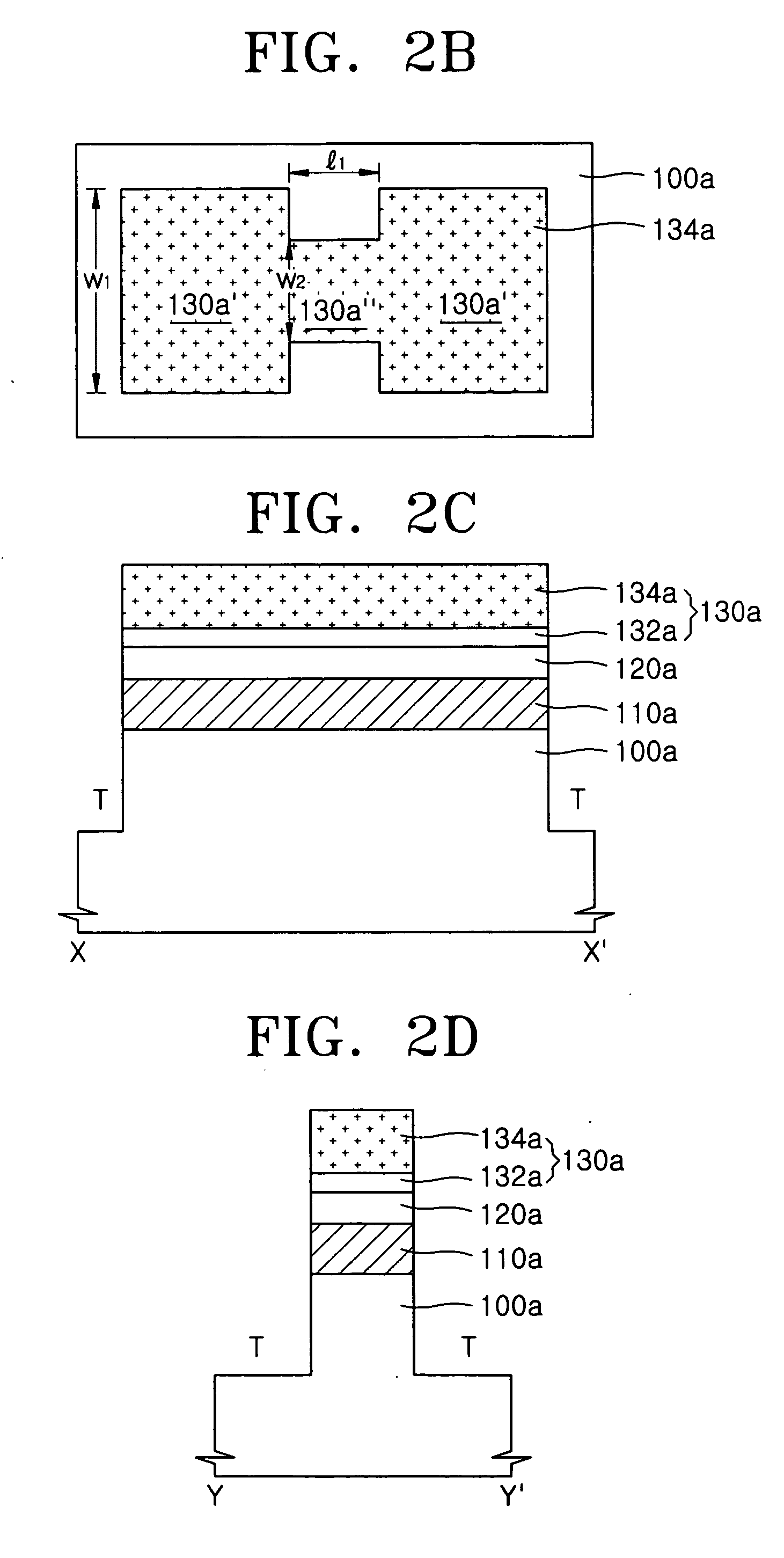
[0009] In some embodiments of the present invention, a field effect transistor (FET) includes spaced apart source and drain regions disposed on a substrate and at least one pair of elongate channel regions (e.g., “wire channel regions”) disposed on the substrate and extending in parallel between the source and drain regions. A gate insulating region surrounds the at least one pair of elongate channel regions, and a gate electrode surrounds the gate insulating region and the at least one pair of elongate channel regions. Support patterns may be interposed between the semiconductor substrate and the source and drain regions. The elongate channel regions may have sufficiently small cross-section to enable complete depletion thereof. For example, a width and a thickness of the elongate channel regions may be in a range from about 10 nanometers to about 20 nanometers. The elongate channel regions may have rounded cross-sections, e.g., each of the elongate channel regions may have an elliptical cross-section. The at least one pair of elongate channel regions may include a plurality of stacked pairs of elongate channel regions.

Problems solved by technology

Thus, a semiconductor device including the conventional MOS transistor having the MBC structure may not operate desirably at high speed.
This problem may also occur in MOS transistors having the other aforementioned channel structures.
In addition, there may be a limit to the number of spaced channel layers that may be included in a conventional MOS transistor having an MBC structure due to limits on etching depth that can be achieved during dry etching.
The limit to the number of channel layers may prevent improvement of the performance and reliability of an MBC MOS transistor.

Method used


Image

  • Multi bridge channel field effect transistors with nano-wire channels and methods of manufacturing the same
  • Multi bridge channel field effect transistors with nano-wire channels and methods of manufacturing the same
  • Multi bridge channel field effect transistors with nano-wire channels and methods of manufacturing the same

Examples


Embodiment Construction

[0025] The present invention now will be described more fully hereinafter with reference to the accompanying drawings, in which embodiments of the invention are shown. However, this invention should not be construed as limited to the embodiments set forth herein. Rather, these embodiments are provided so that this disclosure will be thorough and complete, and will fully convey the scope of the invention to those skilled in the art. In the drawings, the thickness of layers and regions are exaggerated for clarity. Like numbers refer to like elements throughout. As used herein the term “and / or” includes any and all combinations of one or more of the associated listed items.

[0026] The terminology used herein is for the purpose of describing particular embodiments and is not intended to be limiting of the invention. As used herein, the singular forms “a”, “an” and “the” are intended to include the plural forms as well, unless the context clearly indicates otherwise. It will be further u...


PUM

PropertyMeasurementUnit
thicknessaaaaaaaaaa
thicknessaaaaaaaaaa
thicknessaaaaaaaaaa

Abstract

A field effect transistor (FET) includes spaced apart source and drain regions disposed on a substrate and at least one pair of elongate channel regions disposed on the substrate and extending in parallel between the source and drain regions. A gate insulating region surrounds the at least one pair of elongate channel regions, and a gate electrode surrounds the gate insulating region and the at least one pair of elongate channel regions. Support patterns may be interposed between the semiconductor substrate and the source and drain regions. The elongate channel regions may have sufficiently small cross-section to enable complete depletion thereof. For example, a width and a thickness of the elongate channel regions may be in a range from about 10 nanometers to about 20 nanometers. The elongate channel regions may have rounded cross-sections, e.g., each of the elongate channel regions may have an elliptical cross-section. The at least one pair of elongate channel regions may include a plurality of stacked pairs of elongate channel regions.

Description

CROSS-REFERENCE TO RELATED APPLICATION [0001] This application claims the benefit of Korean Patent Application No. 10-2004-0086555, filed on Oct. 28, 2004, in the Korean Intellectual Property Office, the disclosure of which is incorporated herein by reference in its entirety. BACKGROUND OF THE INVENTION [0002] The present invention relates to semiconductor devices and methods of manufacturing the same and, more particularly, to field effect transistors (FETs) and methods of manufacturing the same. [0003] As the number of applications of semiconductor devices has increased, demand for highly integrated and / or high-speed semiconductor devices has increased. As the integration of semiconductor devices has increased, design rule has tended to decrease, e.g., channel lengths and channel widths of MOS (metal-oxide-semiconductor) transistors have decreased. [0004] When channel length decreases, a short channel effect can occur, and when the channel width decreases, a narrow width effect ca...

Claims


Application Information

Patent Timeline
Patent Type & Authority Applications(United States)
IPC IPC(8): H01L29/76H01L21/336
CPCH01L29/78696B82Y10/00H01L29/0665H01L29/0673H01L29/1029H01L29/42392H01L29/66545H01L29/66772H01L29/78654
Inventor LI, MINGKIM, SUNG-MIN
Owner SAMSUNG ELECTRONICS CO LTD
Why Eureka
Try Eureka