[0012] In the current sensor according to the invention, as compared with the case where the conductor and the first and second magnetoresistive elements are provided in the same level, the conductor and the first and second magnetoresistive elements are provided closer to each other. Consequently, the dimensions of the whole are reduced, and the current magnetic
field based on the current to be detected which flows in the conductor is supplied to the first and second magnetoresistive elements more strongly.
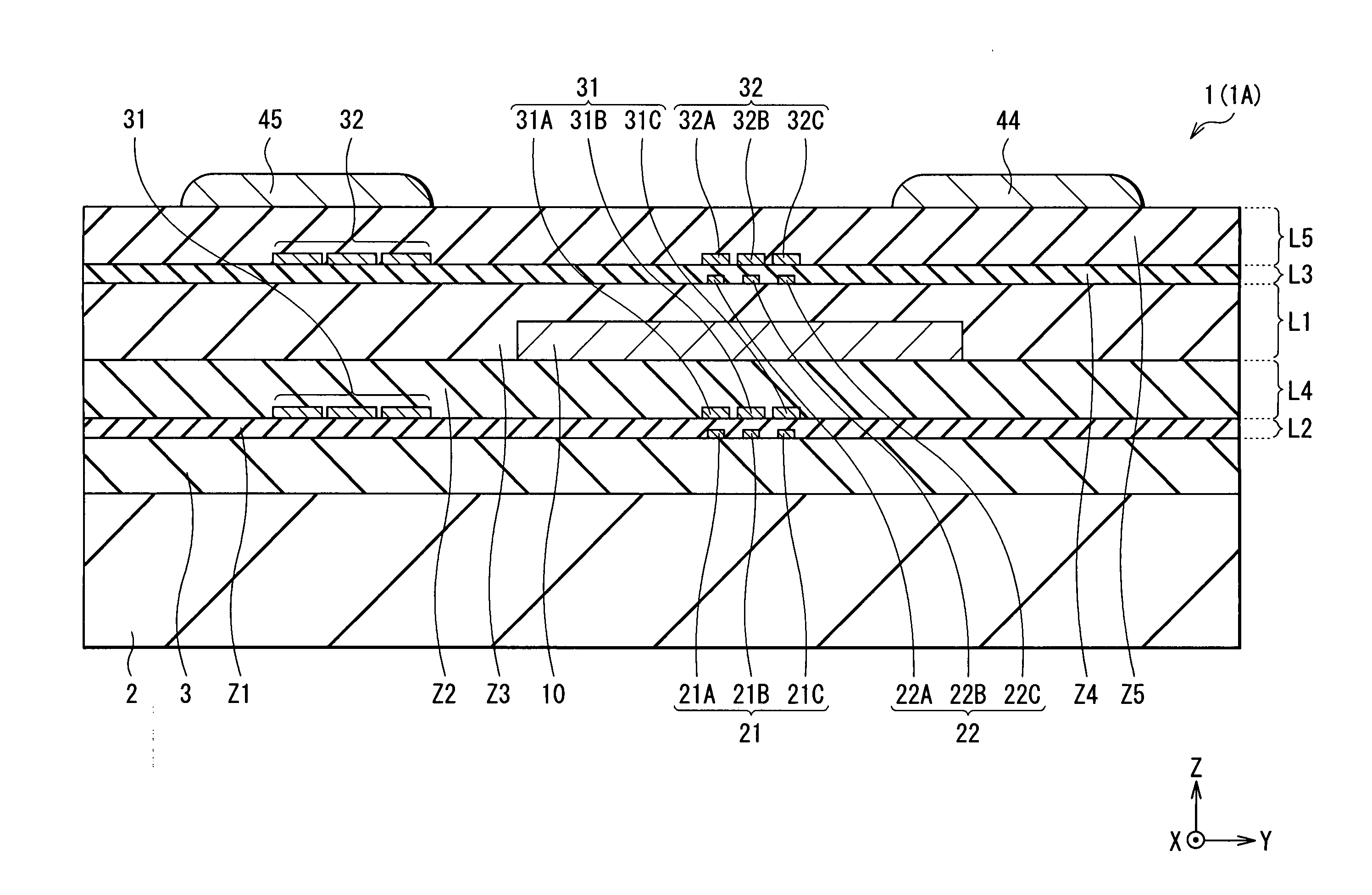
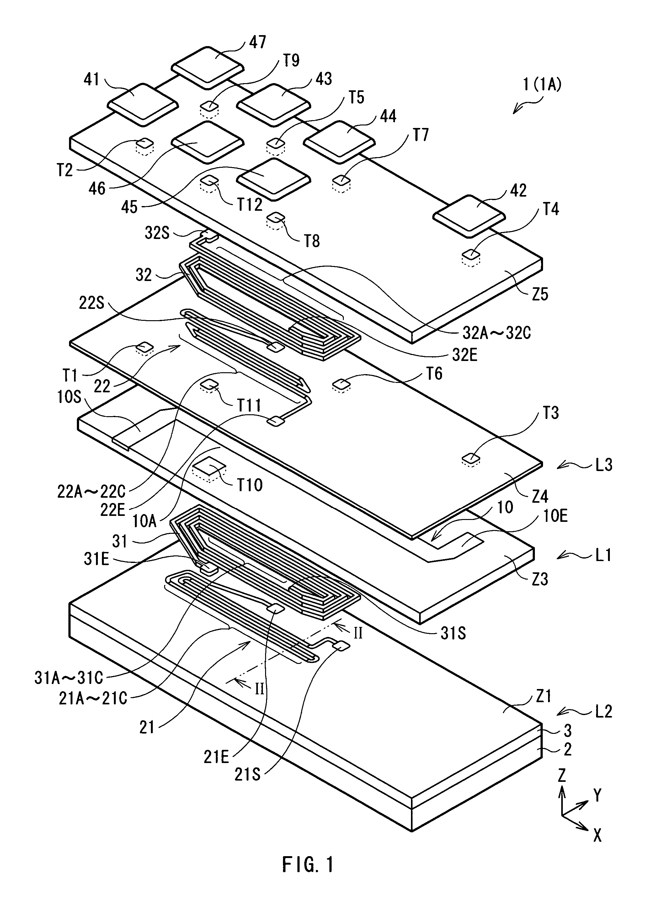
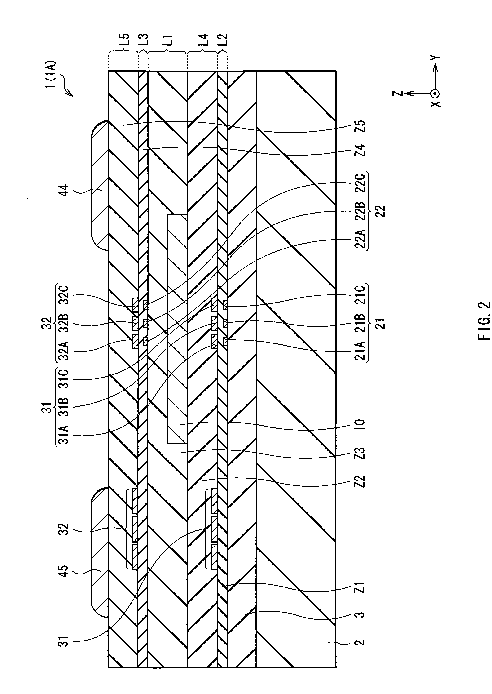
[0017] The current sensor of the invention has: the conductor extending in the first direction at the first level and to which the current to be detected is supplied; the first magnetoresistive element extending in the first direction in the area corresponding to the conductor at the second level; and the second magnetoresistive element extending in the first direction in the area corresponding to the conductor at the third level positioned on the side opposite to the second level with respect to the first level as a reference and whose resistance value changes in the direction opposite to that of the first magnetoresistive element in accordance with the current magnetic field. Consequently, while realizing compactness, the current magnetic field generated by the current to be detected can be detected with high sensitivity. Therefore, while realizing the compact configuration, a relatively
weak current to be detected can be measured with high precision. Since the resistance value in the first magnetoresistive element and that in the second magnetoresistive element change in the directions opposite to each other by the current magnetic field, by detecting the difference between the resistance values, the current to be detected can be measured with high precision. In particular, by detecting the difference between
voltage drops which occur when the constant currents having values equal to each other are passed to the first and second magnetoresistive elements, reliability of the result of measurement improves.
[0018] By further providing the current sensor of the present invention with: the first compensating current line provided in a region corresponding to the first magnetoresistive element at a fourth level, and applying a compensating current magnetic field in the direction opposite to that of a current magnetic field applied to the first magnetoresistive element on the basis of the current to be detected when a compensating current according to the
voltage drop difference flows, to the first magnetoresistive element; and the second compensating current line provided in a region corresponding to the third magnetoresistive element at a fifth level, and applying a compensating current magnetic field in the direction opposite to that of a current magnetic field applied to the second magnetoresistive element on the basis of the current to be detected when a compensating current according to the
voltage drop difference flows, to the second magnetoresistive element, an error caused by variations in the characteristics between the first and second magnetoresistive elements, variations in the connection resistance in the circuit, or a bias in the temperature distribution can be canceled. Accordingly, the current to be detected can be measured with higher precision.
[0019] In the current sensor of the invention, particularly, when each of the first and second magnetoresistive elements has a plurality of element patterns disposed so as to be adjacent to each other in the second direction orthogonal to the first direction and connected in series, without increasing the dimension in the first direction, the total length of each of the element patterns functioning as magnetosensitive parts can be obtained, and the absolute value of the whole resistance value (impedance) in each of the first and second magnetoresistive elements can be obtained. Therefore, even a weaker current to be detected can be measured with high precision. When the first compensating current line includes a plurality of winding body portions extending in the first direction in correspondence with the element patterns in the first magnetoresistive element and winds in the fourth level, and the second compensating current line includes a plurality of winding body portions extending in the first direction in correspondence with element patterns in the second magnetoresistive element, the compensating current magnetic fields Hd having uniform magnitude can be applied to each of the plurality of element patterns, and precision of measurement values of the current to be detected can be further increased.
[0020] In the current sensor of the invention, particularly, when each the first and second magnetoresistive elements has a plurality of element patterns disposed so as to be adjacent to each other in a second direction and connected in parallel with each other, while maintaining a compact configuration, the whole resistance value (impedance) can be decreased without decreasing the resistance change ratio, the influence by
noise from the outside (unnecessary magnetic fields) is reduced, and the S / N ratio can be improved. In this case as well, when the first compensating current line winds in the fourth level so as to include the plurality of winding body portions extending in the first direction in correspondence with the element patterns in the first magnetoresistive element and the second compensating current line winds in the fifth level so as to include the winding body portions extending in the first direction in correspondence with the element patterns in the second magnetoresistive element, the compensating current magnetic field of a proper magnitude can be supplied to each of the plurality of element patterns, and precision of measurement values of the current to be detected can be further increased.
[0021] When the current sensor of the invention further includes: the third magnetoresistive element which extends in the first direction in a region corresponding to the conductor at the second level, other than the region in which the first magnetoresistive element is formed, and whose resistance value changes in the same direction as that in the first magnetoresistive element in accordance with the current magnetic field; and the fourth magnetoresistive element which extends in the first direction in a region corresponding to the conductor at the third level, other than the region in which the second magnetoresistive element is formed, and whose resistance value changes in the direction opposite to that in the first magnetoresistive element in accordance with the current magnetic field, a
bridge circuit can be constructed by using first to fourth magnetoresistive elements. While maintaining the compact configuration, precision of measurement values of the current to be detected can be further increased.

