Optical position assessment apparatus and method

Active Publication Date: 2006-05-04
ASML NETHERLANDS BV
View PDF28 Cites 91 Cited by
  • Summary
  • Abstract
  • Description
  • Claims
  • Application Information

AI Technical Summary

Benefits of technology

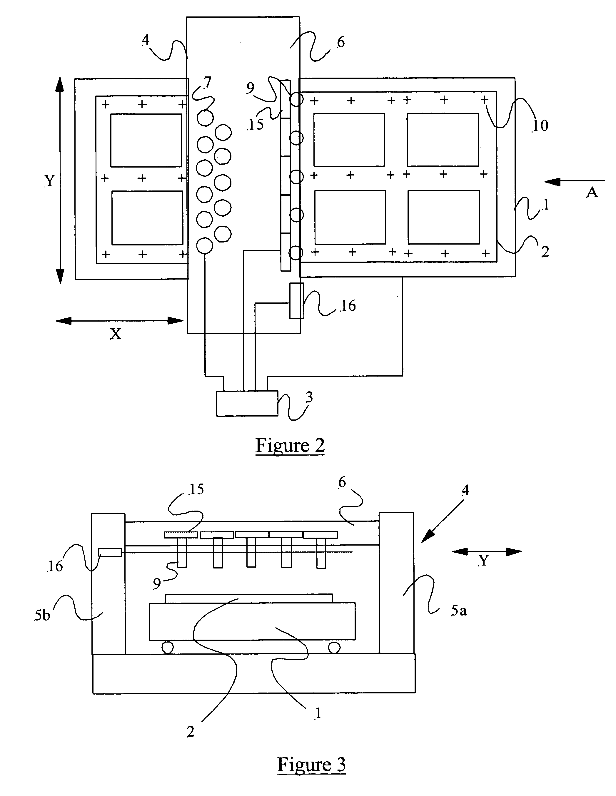
[0013] In this embodiment, the invention makes it possible to use a single lithographic apparatus, in a stable operating configuration, for the production of panels or other devices having variable dimensions. Alignment mark detectors can be moved relative to the frame supporting the detectors and the projection sys

Problems solved by technology

This has meant that, for non-standard panel layouts, either only alignment marks around the periphery of the substrate can be used (as the periphery is the only “blank” region common to all substrate layouts), or some manual realignment of the detectors must be carried out While a continuous array of alignment mark detectors positioned across the substrate to detect al

Method used


Image

  • Optical position assessment apparatus and method
  • Optical position assessment apparatus and method
  • Optical position assessment apparatus and method

Examples


Embodiment Construction

Overview and Terminology

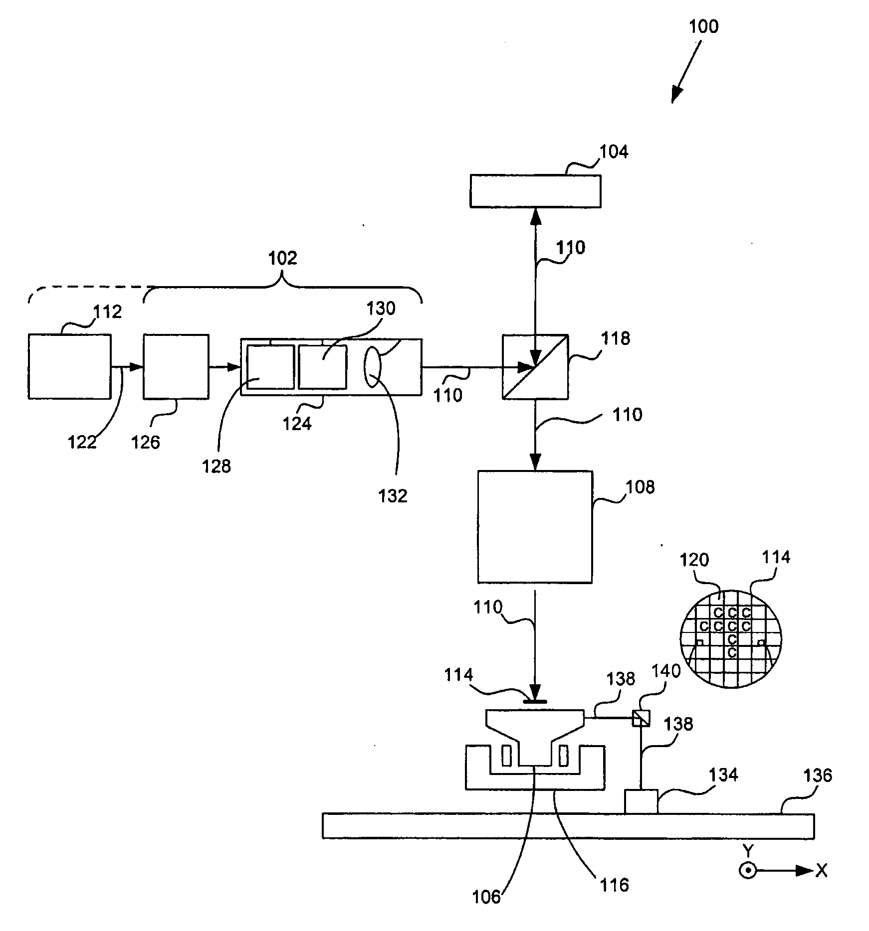
[0034] Although specific reference can be made in this text to the use of lithographic apparatus in the manufacture of integrated circuits (ICs), it should be understood that the lithographic apparatus described herein can have other applications, such as the manufacture of integrated optical systems, guidance and detection patterns for magnetic domain memories, flat panel displays, thin-film magnetic heads, etc. The skilled artisan will appreciate that, in the context of such alternative applications, any use of the terms “wafer” or “die” herein can be considered as synonymous with the more general terms “substrate” or “target portion,” respectively. The substrate referred to herein can be processed, before or after exposure, in for example a track (e.g., a tool that typically applies a layer of resist to a substrate and develops the exposed resist) or a metrology or inspection tool. Where applicable, the disclosure herein can be applied to such and other ...


PUM


Abstract

A lithographic apparatus comprises a substrate table that supports a substrate having alignment marks on a surface thereof. The apparatus further comprises a frame moveable relative to the substrate to provide for a scanning or stepping mode of operation. An array of projection systems is disposed across the frame for projecting respective patterned beams onto a target portion of the substrate. A plurality of alignment mark detectors are attached to the frame and are moveable with respect to the frame using respective linear drive mechanisms. A position sensor is associated with each alignment mark detector for determining the position of the detector relative to the frame. A control system is responsible for both initial positioning of the detectors above alignment mark patterns on the substrate, and for dynamic alignment of the frame and substrate during a lithographic process.

Description

BACKGROUND OF THE INVENTION [0001] 1. Field of the Invention [0002] The present invention relates to a lithographic apparatus and a device manufacturing method. [0003] 2. Related Art [0004] A lithographic apparatus is a machine that applies a desired pattern onto a target portion of a substrate. The lithographic apparatus can be used, for example, in the manufacture of integrated circuits (ICs), flat panel displays, and other devices involving fine structures. In a conventional lithographic apparatus, a patterning means, which is alternatively referred to as a mask or a reticle, can be used to generate a circuit pattern corresponding to an individual layer of the IC (or other device), and this pattern can be imaged onto a target portion (e.g., comprising part of one or several dies) on a substrate (e.g., a silicon wafer or glass plate) that has a layer of radiation-sensitive material (e.g., resist). Instead of a mask, the patterning means can comprise an array of individually contro...

Claims


Application Information

Patent Timeline
IPC IPC(8): G01B11/00
CPCG03F7/70216G03F7/70425G03F9/7088G03F7/20G03F9/00
Inventor GUI, CHENG-QUN
Owner ASML NETHERLANDS BV
Why Eureka
Try Eureka