Condenser microphone

a condenser microphone and microphone body technology, applied in the field of condenser microphones, can solve the problems of insufficient shielding effect and inability to guarantee that the resistivity of the surface must decrease, so as to achieve the effect of stable shielding function improved surface strength of the microphone case, and effective prevention of noise generation

Inactive Publication Date: 2006-05-04
AUDIO-TECHNICA
View PDF4 Cites 0 Cited by
  • Summary
  • Abstract
  • Description
  • Claims
  • Application Information

AI Technical Summary

Benefits of technology

[0008] Accordingly, an object of the present invention is to provide a condenser microphone having a microphone case formed by a casting, the microphone case having a surely decreased surface resistivity and hence having a stable shielding function.
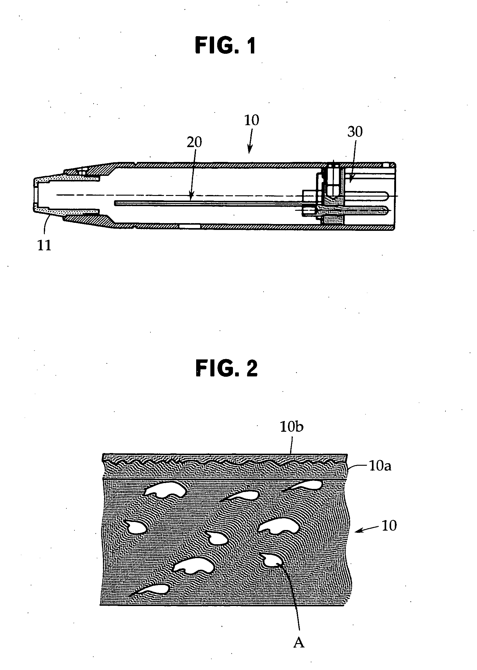
[0011] According to the above-described configuration, since the conductive layer having a low resistivity is formed integrally on the casting surface on the outer surface side of the microphone case, a high frequency current due to electromagnetic waves flows easily on the outer surface of the microphone case due to the skin effect. As a result, the shielding function of the microphone case becomes stable, and noise can be effectively prevented from being generated by the intrusion of electromagnetic waves into the microphone. Also, the surface strength of the microphone case can be increased.

Problems solved by technology

Usually, the microphone case is manufactured by casting (die casting) of zinc, aluminum, etc. from the viewpoint of workability of microphone case and cost constraints, and the resistivity of casting surface is increased by an oxide film as compared with the base material, so that a sufficient shielding effect cannot be achieved.
However, usually, since a casting has blowholes therein due to a gas at the time of casting operation, even if the surface is cut, there is no guarantee that the resistivity of the surface necessarily decrease.

Method used


Image

  • Condenser microphone
  • Condenser microphone

Examples


Embodiment Construction

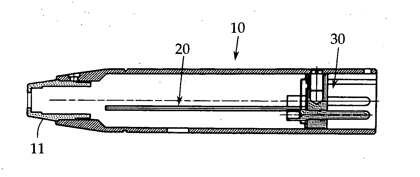
[0014] An embodiment of the present invention will now be described with reference to FIGS. 1 and 2. The present invention is not limited to this embodiment. FIG. 1 is a sectional view showing one example of a microphone case that a condenser microphone in accordance with the present invention has, and FIG. 2 is a partially enlarged sectional view of the microphone case shown in FIG. 1.

[0015] A microphone case 10 shown in FIG. 1 is, as in the case of a gooseneck microphone or a tie clip microphone, a microphone case used for an audio output module section of a separate condenser microphone in which a condenser microphone unit and the audio output module section are connected to each other via a microphone cable.

[0016] The illustration of the condenser microphone unit is omitted because the condenser microphone unit may be a publicly known one. Also, the audio output module section is also called a power module section because it is provided with a polarization power supply circuit...


PUM


Abstract

In a condenser microphone having a microphone case formed by a casting, the resistivity of the surface of the microphone case is decreased surely, and the shielding function of the microphone case is made stable. In a condenser microphone in which a substrate including an audio output circuit connected to a condenser microphone unit is housed therein, and a cylindrical microphone case 10 mounted with an output connector is provided on one end side, the microphone case 10 being formed by casting, a conductive layer 10b having a lower resistivity than that of a raw material of the microphone case 10 is formed integrally on a casting surface 10a on the outer surface side of the microphone case 10.

Description

TECHNICAL FIELD [0001] The present invention relates to a condenser microphone and, more particularly, to a microphone case thereof. BACKGROUND ART [0002] A condenser microphone includes a microphone unit in which a diaphragm and a backplate are arranged so as to be opposed to each other. The microphone unit incorporates an impedance converter because of its very high impedance. As the impedance converter, a field effect transistor (FET) is usually used, and on rare occasions, a vacuum tube is used. [0003] An electronic circuit for audio output of the condenser microphone is housed in a metallic microphone case in a state of being mounted on a substrate. Usually, at one end of the microphone case, a three-pin type output connector specified in EIAJ RC5236 (Audio latch lock round type connector) is mounted. The output connector is connected to a phantom power source via an output cable (balanced shielded cable). [0004] If strong electromagnetic waves radiated from a cellular phone or...

Claims


Application Information

Patent Timeline
Patent Type & Authority Applications(United States)
IPC IPC(8): H04R25/00
CPCH04R1/021H04R19/005H04R19/04
Inventor AKINO, HIROSHI
Owner AUDIO-TECHNICA
Why Eureka
Try Eureka