Loop-back wavelength division multiplexing passive optical network

a passive optical network and wavelength division technology, applied in the field of passive optical networks, can solve the problems of difficulty in implementation, limitation of providing a quality-guaranteed bandwidth of more than 100 mb/s to subscribers, and expected difficulty in ensuring sufficient bandwidth of dsl and cmts technologies, and achieve the effect of easy determination

Inactive Publication Date: 2006-05-04
ELECTRONICS & TELECOMM RES INST
View PDF7 Cites 43 Cited by
  • Summary
  • Abstract
  • Description
  • Claims
  • Application Information

AI Technical Summary

Benefits of technology

[0012] Accordingly, the present invention has been made maintaining in mind the above problems occurring in the prior art, and an object of the present invention is to provide a system and method for

Problems solved by technology

It is expected to be difficult for such DSL and CMTS technologies to guarantee sufficient bandwidth and quality to provide voice, data and broadcast convergence service, which will be popularized within a few years, to subscribers.
In the two above-described types of FTTH networks, a data transmission optical transmission path is constructed on a single wavelength per transmission direction basis, which has a limitation in providing a quality-guaranteed bandwidth of more than 100 Mb/s to subscribers.
However, the WDM-PON requires light sources having intrinsic wavelengths the number of which is identical to the number of subscribers, so that an economical burden is imposed on a service provider and, therefore, there is difficulty in implementation.
In terms of the maintenance of parts, the fact that the service provider must prepare different light sources having different wavelengths for individual subscribers to provide for installation and breakdowns may impose a burden on the service provider.
However, the spectrum-sliced light source is disadvantageous in that the output power and modulation speed thereof are low.
However, the ASE injected FP-LD is expensive and separate temperature control is required for the FP-LD of an optical network terminal.
However, since the Mach-

Method used


Image

  • Loop-back wavelength division multiplexing passive optical network
  • Loop-back wavelength division multiplexing passive optical network
  • Loop-back wavelength division multiplexing passive optical network

Examples


first embodiment

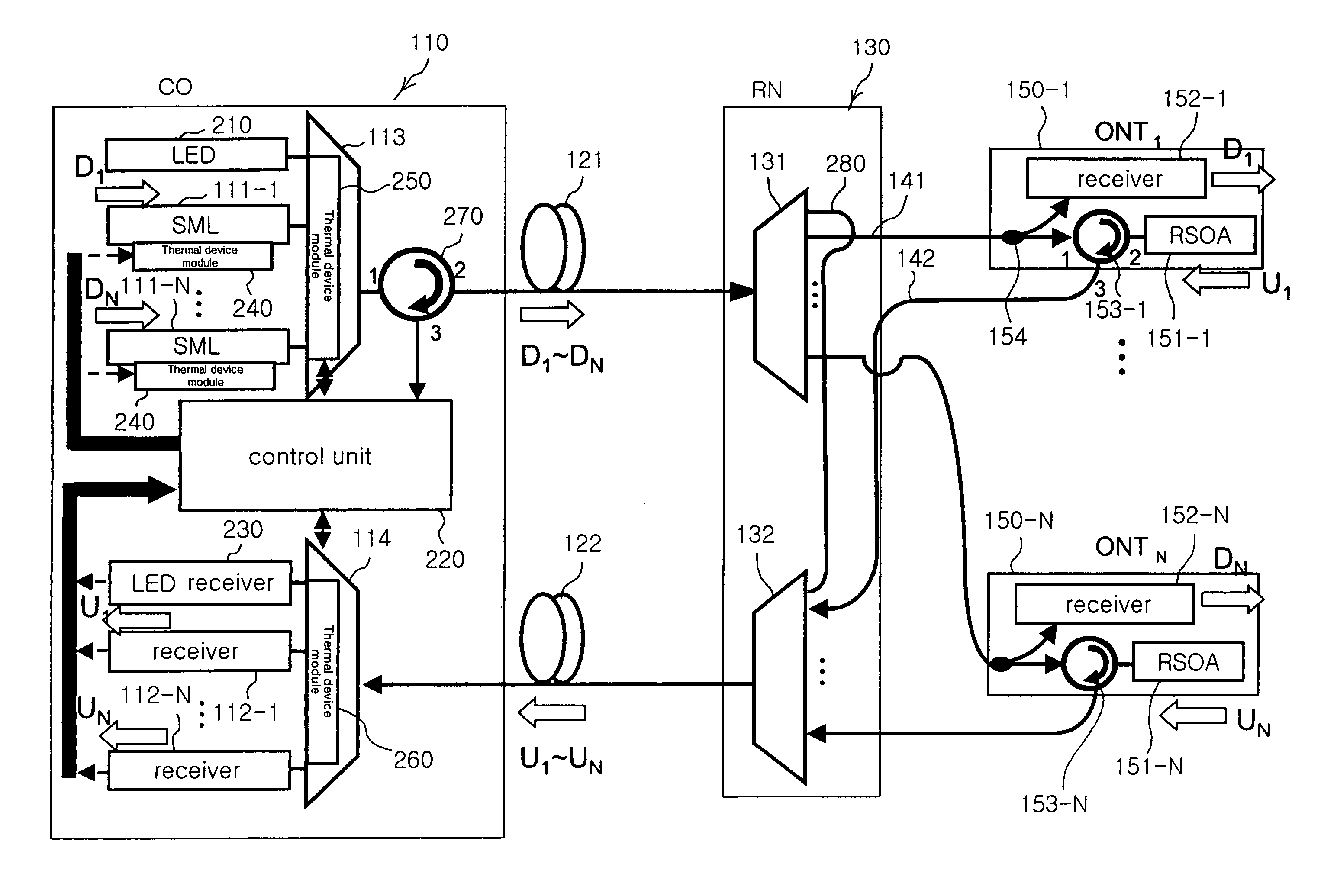
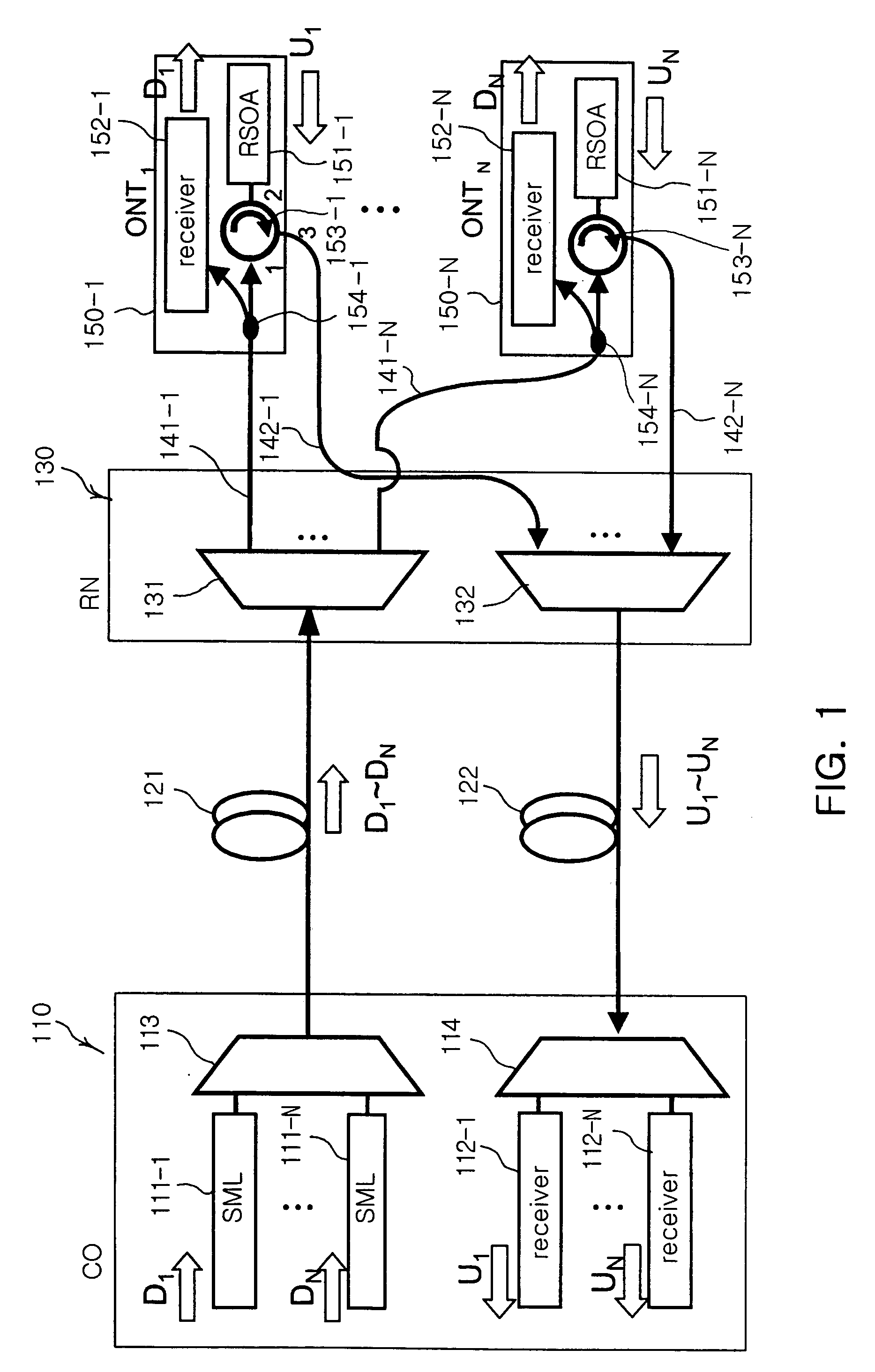
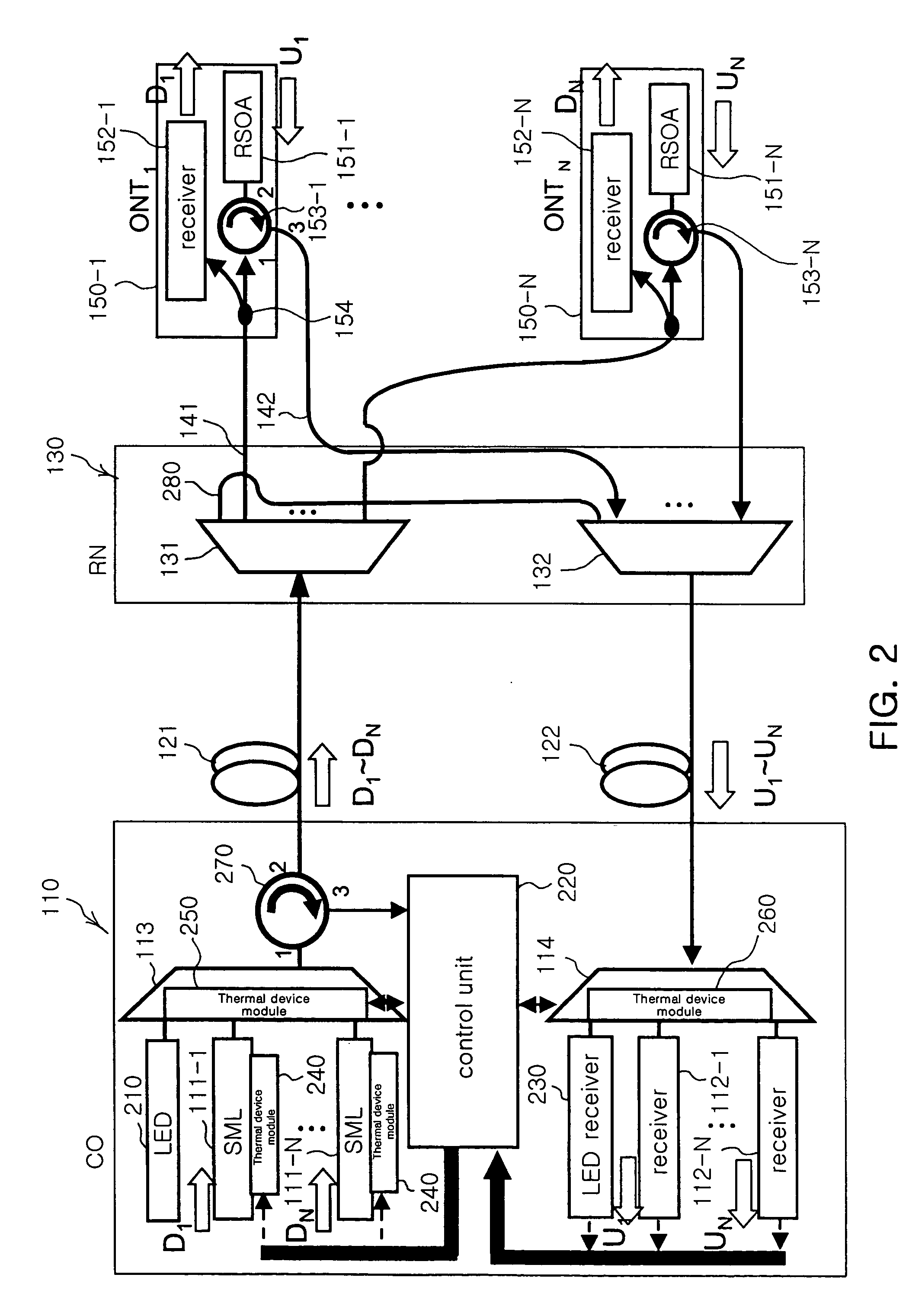
[0043]FIG. 1 is a diagram illustrating the configuration of a loop-back WDM-PON according to the present invention.

[0044] Referring to FIG. 1, an RSOA-based loop-back WDM-PON system according to the first embodiment of the present invention includes a central office (CO) 110, downstream and upstream optical fibers 121 and 122, a remote node (RN) 130, downstream signal optical fibers 141-1 to 141-N, upstream signal optical fibers 142-1 to 142-N, and optical network terminals (ONTs) 150-1 to 150-N.

[0045] The central office 110 includes central office light sources 111-1 to 111-N, central office receivers 112-1 to 112-N, a central office optical multiplexer 113, and a central office optical demultiplexer 114. For example, Single Mode Laser diodes (SMLDs), such as Distributed Feedback Laser Diodes (DFB-LDs), may be used as the central office light sources 111-1 to 111-N, and are constructed separately or in an integrated array form. The single mode laser diodes modulate electrical sign...


PUM


Abstract

Disclosed herein is an apparatus and method for managing faults of a loop-back Wavelength Division Multiplexing Passive Optical Network (WDM-PON). The apparatus includes a control light source as well as a plurality of light sources in a central office, a loop-back means for transmitting control light to the central office through a remote node optical demultiplexer or remote node optical multiplexer in a remote node, a control light receiver for receiving looped-back control light, and a control unit for maintaining power of the upstream signals, which are received by central office receivers, and power of the control light, which is received by the control light receiver, at a maximum.

Description

RELATED APPLICATIONS [0001] The present application is based on, and claims priority from, Korean Application Number 2004-0087926, filed Nov. 1, 2004, the disclosure of which is incorporated by reference herein in its entirety. BACKGROUND OF THE INVENTION [0002] 1. Field of the Invention [0003] The present invention relates generally to a passive optical network and, more particularly, to a system and method for managing the faults of a passive optical network that uses loop-back wavelength division multiplexing. [0004] 2. Description of the Related Art [0005] Currently, a Digital Subscriber Line (DSL) technology using an Unshielded Twisted Pair (UTP) and a Cable Modem Termination System (CMTS) technology using a Hybrid Fiber Coaxial (HFC) network have been widely used as information transmission technologies for communication systems. It is expected to be difficult for such DSL and CMTS technologies to guarantee sufficient bandwidth and quality to provide voice, data and broadcast ...

Claims


Application Information

Patent Timeline
IPC IPC(8): H04J14/00
CPCH04B10/2587H04B10/27H04J14/0226H04J14/0282H04J14/0246H04J14/025H04J2014/0253H04B10/03H04B10/035H04B10/2581
Inventor LEE, WOO RAMCHO, SEUNG HYUNKIM, BYOUNG WHIPARK, JAE DONG
Owner ELECTRONICS & TELECOMM RES INST
Why Eureka
Try Eureka