
Heat developing method and heat developing apparatus

a heat development and heat development technology, applied in the field of heat development methods and heat development apparatuses, can solve the problems of not suggesting and revealing measures for a rapid heat development process, and achieve the effect of stabilizing density and stabilizing image quality

Inactive Publication Date: 2006-05-11
KONICA MINOLTA MEDICAL & GRAPHICS INC
View PDF5 Cites 6 Cited by
  • Summary
  • Abstract
  • Description
  • Claims
  • Application Information

AI Technical Summary

Benefits of technology

[0009] The present invention is originated to eliminate the difficulties of the prior arts mentioned above and is intended to provide a heat developing method and a heat developing apparatus, when executing a heat developing process by a rapid process of 10 seconds or less, for stabilizing the density and making the image quality stable.
[0012] According to the heat developing apparatus, when executing the heat developing process by the rapid process of 10 seconds or less, the EC side is opened, and the sheet film is heated from the BC side, thus the solvents (moisture, organic solvent, etc.) contained in the sheet film which are heated and are intended to volatilize (evaporate) are almost scattered out at the shortest distance, so that even if the heating time (volatilization time) is shortened, the sheet film is unlikely to be affected by the shortened time, and the image quality is stabilized, and even if there is a part where the contact between the film and the heating body is not enough, a density difference from the part where the contact is satisfactory is unlikely to appear, so that the density can be stabilized, and the image quality becomes stable. Further, after end of the heating step, the sheet film is cooled from the support body face by opening the EC side, and moreover the EC side is opened between the heating section and the cooling section, so that the solvents (moisture, organic solvent, etc.) still at a high temperature which are intended to volatilize (evaporate) are not trapped and are volatilized for a longer period of time, so that the image quality (density, γ curve) is stabilized. In the rapid process, this time cannot be ignored and it is particularly valid in a rapid process of a heating time of 10 seconds or less.
[0013] Further, according to this developing apparatus, the aforementioned heat developing method can be executed, and the EC side is opened, and the sheet film is heated from the BC side, and the heated sheet film is conveyed to the cooling section by opening the EC side in the upward direction opposite to the gravity direction, thus the solvents are easily volatilized at the shortest distance from the sheet film heated during the conveyance of heating and cooling, and a difference is unlikely to appear in the density, and the density is stabilized more.
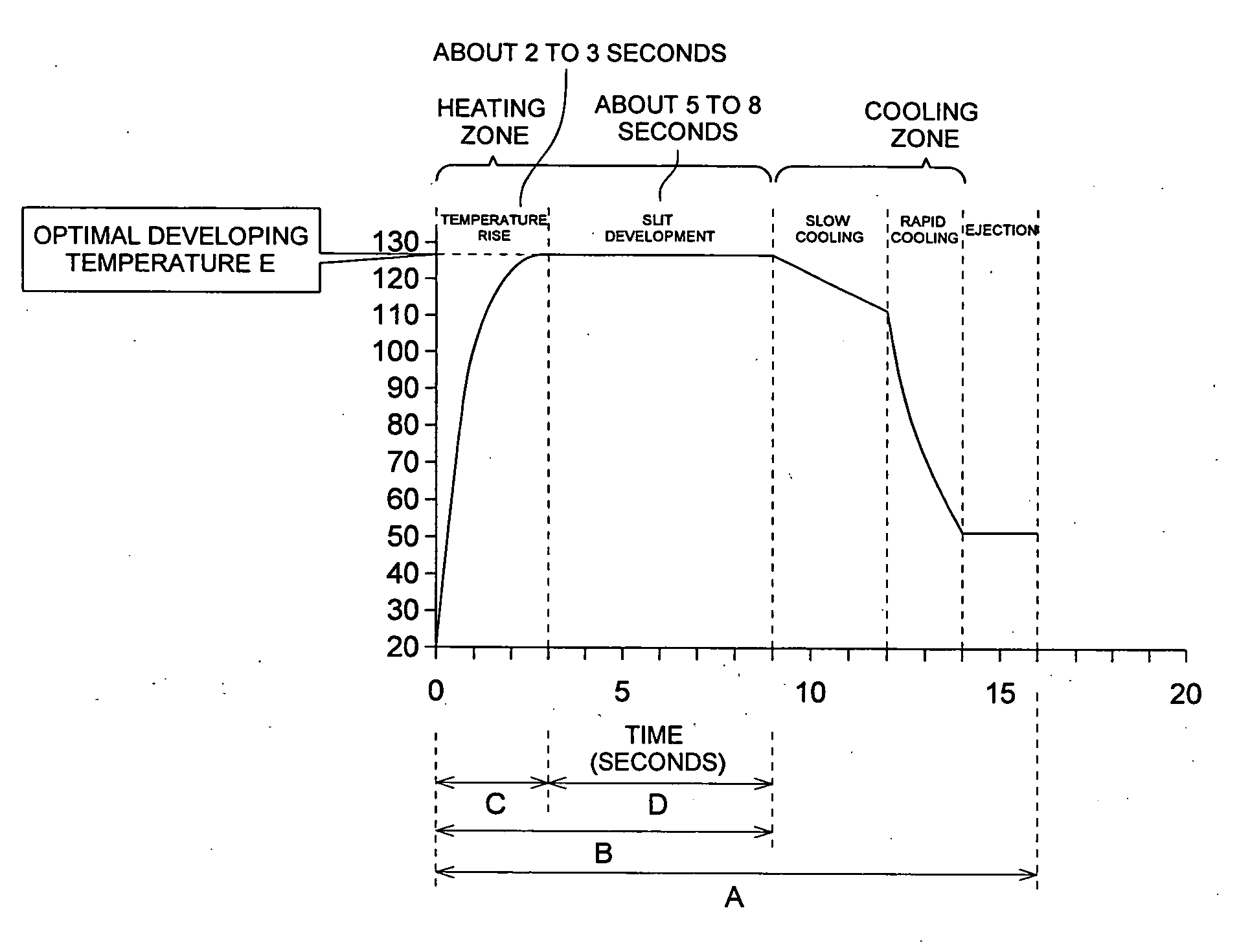
[0015] In the heat developing apparatus aforementioned, the cooling section is preferably structured at least on the sheet film entering side so as to open the EC side. On the sheet film entering side, the solvents (moisture, organic solvent, etc.) are still at a high temperature, as the EC side is opened, the solvents are not trapped and can be volatilized for a longer period of time.
[0016] Further, the heating section is structured so as to execute the temperature raising step of raising the sheet film to the heat developing temperature and the temperature retaining step of retaining the temperature of the sheet film raised to the heat developing temperature, thus uneven density is more unlikely to be generated.
[0018] According to the heat developing method and heat developing apparatus of the present invention, when executing the heat developing process by the rapid process of 10 seconds or less, the density can be stabilized and the image quality can be made stable. Further, in consideration of stable conveyance of sheet films, the lower limit of the heating time is about 5 seconds.

Problems solved by technology

However, in Patent Documents 1 and 2, no measures for a rapid heat developing process are suggested and disclosed.

Method used


Image

  • Heat developing method and heat developing apparatus
  • Heat developing method and heat developing apparatus
  • Heat developing method and heat developing apparatus

Examples


first embodiment

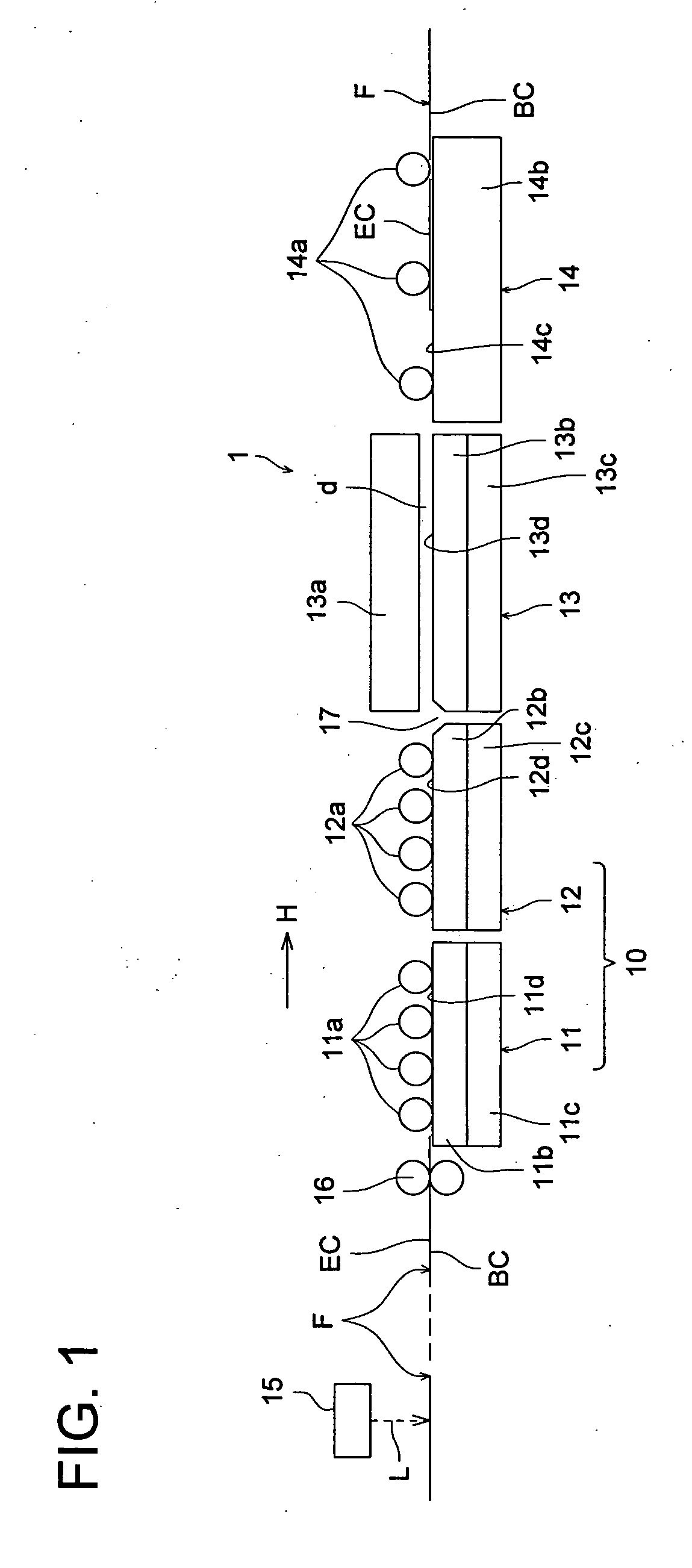
[0055]FIG. 1 is a side view schematically showing the essential section of the heat developing apparatus of the first embodiment. As shown in FIG. 1, a heat developing apparatus 1 of the first embodiment, by sub-scanning and conveying a sheet film F (hereinafter, referred to as a film) having an EC side on one side of a sheet support base made of PET and a BC side of the opposite face of the EC side in the direction H, scans and exposes a laser beam L by an optical scanning exposure unit 15 on the basis of image data, thereby forms a latent image on the EC side, then heats and develops the film F from the BC side, and makes the latent image visible.

[0056] The heat developing apparatus 1 shown in FIG. 1 includes a temperature raising unit 10 for heating the film F having a formed latent image from the BC side and raising it up to a predetermined heat developing temperature, a temperature retaining unit 13 for heating and retaining the film at the predetermined heat developing temper...

second embodiment

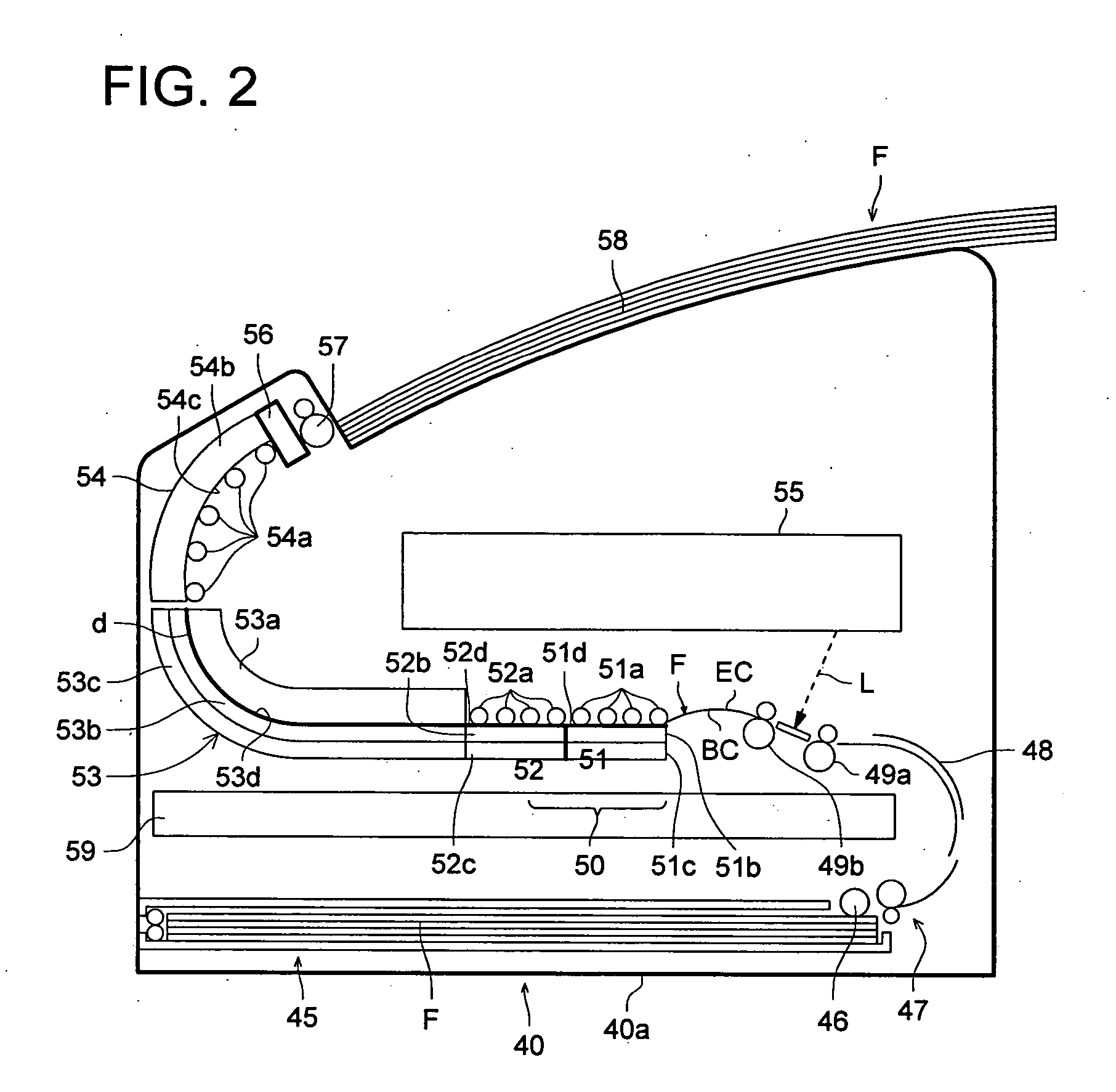
[0074]FIG. 2 is a side view schematically showing the essential section of the heat developing apparatus of the second embodiment.

[0075] As shown in FIG. 2, a heat developing apparatus 40 of the second embodiment, similarly to the aforementioned, by sub-scanning and conveying the sheet film F having the EC side on one side of the sheet support base made of PET and the BC side of the opposite face of the EC side, forms a latent image on the EC side by a laser beam L from an optical scanning exposure unit 55, then heats and develops the film F from the BC side, makes the latent image visible, and conveys and ejects it above the apparatus via the curved conveying path.

[0076] The heat developing apparatus 40 shown in FIG. 2 includes a film storage unit 45 for storing many unused films F installed in the neighborhood of the bottom of an apparatus frame 40a, a pickup roller 46 for picking up and conveying the uppermost film F of the film storage unit 45, a pair of conveying rollers 47 f...

third embodiment

[0102]FIG. 4 is a side view schematically showing the essential section of the heat developing apparatus of the third embodiment. In FIG. 4, to the elements having the same functions as those of the heat developing apparatus 40 shown in FIG. 2, the same numerals are assigned. As shown in FIG. 4, the heat developing apparatus 41 of this embodiment, by sub-scanning and conveying the sheet film F having the EC side on one side of the sheet support base made of PET and the BC side of the opposite face of the EC side, forms a latent image on the EC side by a laser beam L from the optical scanning exposure unit 55, then heats and develops the film F from the BC side, makes the latent image visible, and conveys and ejects it above the apparatus via the curved conveying path.

[0103] The heat developing apparatus 41 shown in FIG. 4 includes the film storage unit 45 for storing many unused films F installed in the neighborhood of the bottom of the apparatus frame 41a, the pickup roller 46 for...


PUM


Abstract

The present invention provides a heat developing method and a heat developing apparatus for stabilizing density and making image quality stable when executing a heat developing process by a rapid process of 10 seconds or less. The heat developing method is a method for heating a film with a heat developing photosensitive material coated on one side of a support base thereof for a heating time of 10 seconds or less and then cooling it, which opens the face side of the film with the heat developing photosensitive material coated, heats it from the support base side, and cools it from the supports base side by opening the side of the film where the heat developing photosensitive material is coated.

Description

[0001] This application is based on Japanese Patent Application No. 2004-322122 filed on Nov. 5, 2004, No. 2004-322124 filed on Nov. 5, 2004, No. 2004-327337 filed on Nov. 11, 2004, No. 2004-371259 filed on Dec. 22, 2004 and No. 2004-371260 filed on Dec. 22, 2004, in Japanese Patent Office, the entire content of which is hereby incorporated by reference. BACKGROUND OF THE INVENTION [0002] 1. Field of the Invention [0003] The present invention relates to a heat developing method and a heat developing apparatus for a rapid process by heating and then cooling a sheet film with a heat developing photosensitive material coated. [0004] 2. Description of the Related Art [0005] Patent Document 1 indicated below discloses a heat developing apparatus for sliding and heating a sheet film on the EC (emulsion coated) side between a heating drum (heated) having a flexible layer and a plurality of opposing rollers, thereby developing a film with a latent image formed. Patent Document 2 indicated b...

Claims


Application Information

Patent Timeline
IPC IPC(8): B41J2/32
CPCB41J2/32
Inventor KIDO, KAZUHIROUMEKI, MAMORU
Owner KONICA MINOLTA MEDICAL & GRAPHICS INC
Learn More