Functional porous fibres

a technology of porous polymeric fibres and functional fibers, which is applied in the direction of ion exchangers, filtration separation, yarns, etc., can solve the problems of not being able to disclose the other suggestions, casting processes are not suitable for the preparation of fibres, and involving additional process steps

Inactive Publication Date: 2006-05-11
NEOKIDNEY HLDG
View PDF18 Cites 29 Cited by
  • Summary
  • Abstract
  • Description
  • Claims
  • Application Information

AI Technical Summary

Benefits of technology

[0013] It is an object of the invention to provide a porous fibre comprising particulate material having a certain functionality by a process, which can be operated at room temperature or reigned temperatures and does not require additional process steps after the formation of the fibre.

Problems solved by technology

However, besides the embodiment of flow casting a membrane onto a support none of the other suggestions are enabling disclosed.
Such casting processes are not suitable for the preparation of fibres.
Disadvantages of the known porous polymeric fibre preparation processes are that they involve additional process steps after the formation of the fibre to come to a final product.
Obviously such a requirement puts limitations on the polymeric material that can be used.
Furthermore it puts limitations on the type of particulate material that can be comprised in the polymeric matrix.
A high degree of particle loading will reduce the mechanical strength of the fibre and therefore restrict the stretching procedure.
The degree of loading will be limited by the force required to reach sufficient stretching of the matrix material.
% solvent results in rather dense exterior surfaces and limited particle accessibility.
However, an increase in the amount of solvent results in difficulties of controlling the spinning process; due to delayed demixing of the nascent fibre solidification takes too long.

Method used


Image

  • Functional porous fibres
  • Functional porous fibres
  • Functional porous fibres

Examples


example 1

Solid Fibre Polyethylene-Vinyl-Alcohol / Cation Exchange Resin Structure

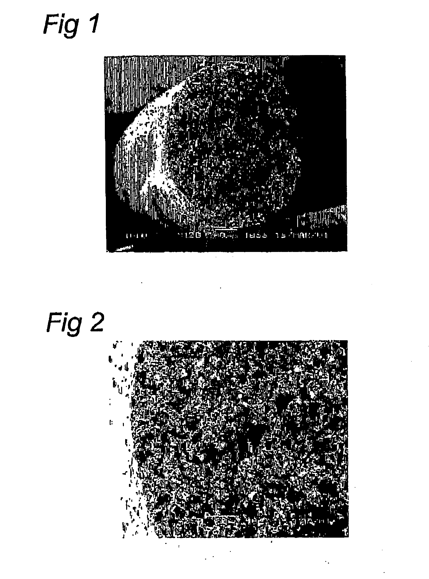
[0066] A polyethylene-vinyl-alcohol (EVAL with 44% ethylene content) solid fiber was produced by dissolving 7 wt. % EVAL and 12 wt. % cation-exchange resin (CER) (Lewatit CNP 80 WS (Bayer), total ion-exchange capacity: 4.3 eq / l) and 7 wt. % octanol in dimethylsulfoxide (DMSO). The resin particles were smaller than 20 μm. The obtained dispersion was extruded through a tube-in-orifice spinneret (OD=2.4 and ID=1.65 mm) into a water bath (20° C.), where phase separation occurred. There was no bore liquid used for the production of solid fibre. This way a porous solid fibre was obtained with a particle load of 60 wt. % CER, with 80% of the immobilised particles being active for protein (BSA) adsorption. A BSA adsorption of 80 mg / g fibre has been obtained.

example 2

Hollow Fibre Polysulfone / Cation Exchange Resin Structure

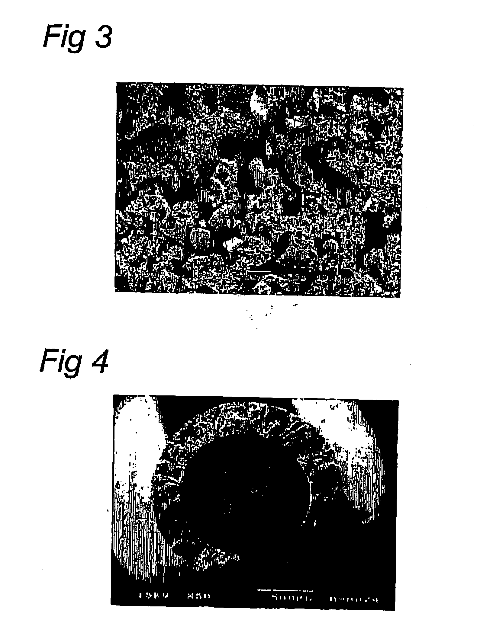
[0067] A polysulfone hollow fibre was produced by dissolving 30 wt. % polysulfone (UDEL 3500) and mixing it with 30 wt. % of the styrene-divinylbenzene type cation-exchange resin (CER) (Amberlite IR-120, total ion-exchange capacity: 4,4 meq / g-dry resin) in N-Methylpyrrolidone (NMP). The resin particles were smaller than 30 μm. This dispersion was extruded through a tube-in-orifice spinneret (OD=2.1 and ID=1.0 mm) into a water bath (16-18° C.), where phase separation occurred. The bore liquid consisted of 60% NMP and 40% water. The spinning rate was 0.35 m / min. This way a porous hollow fibre was obtained with a particle load of 50 wt. % CER, with 88% of the immobilised particles being accessible for salt ions.

[0068] The produced hollow fibre without a post treatment shows a NaOH flux of 7.9 mol.hr.m2 and a Na2SO4 flux of 2.4 mol.hr.m2. This results in a rather low selectivity of 3.3. It appears that a heat treatment of the pr...

example 3

Solid Fibre Polyethylene-Vinyl-Alcohol / BSA-Modified Cation Exchange Resin Structure

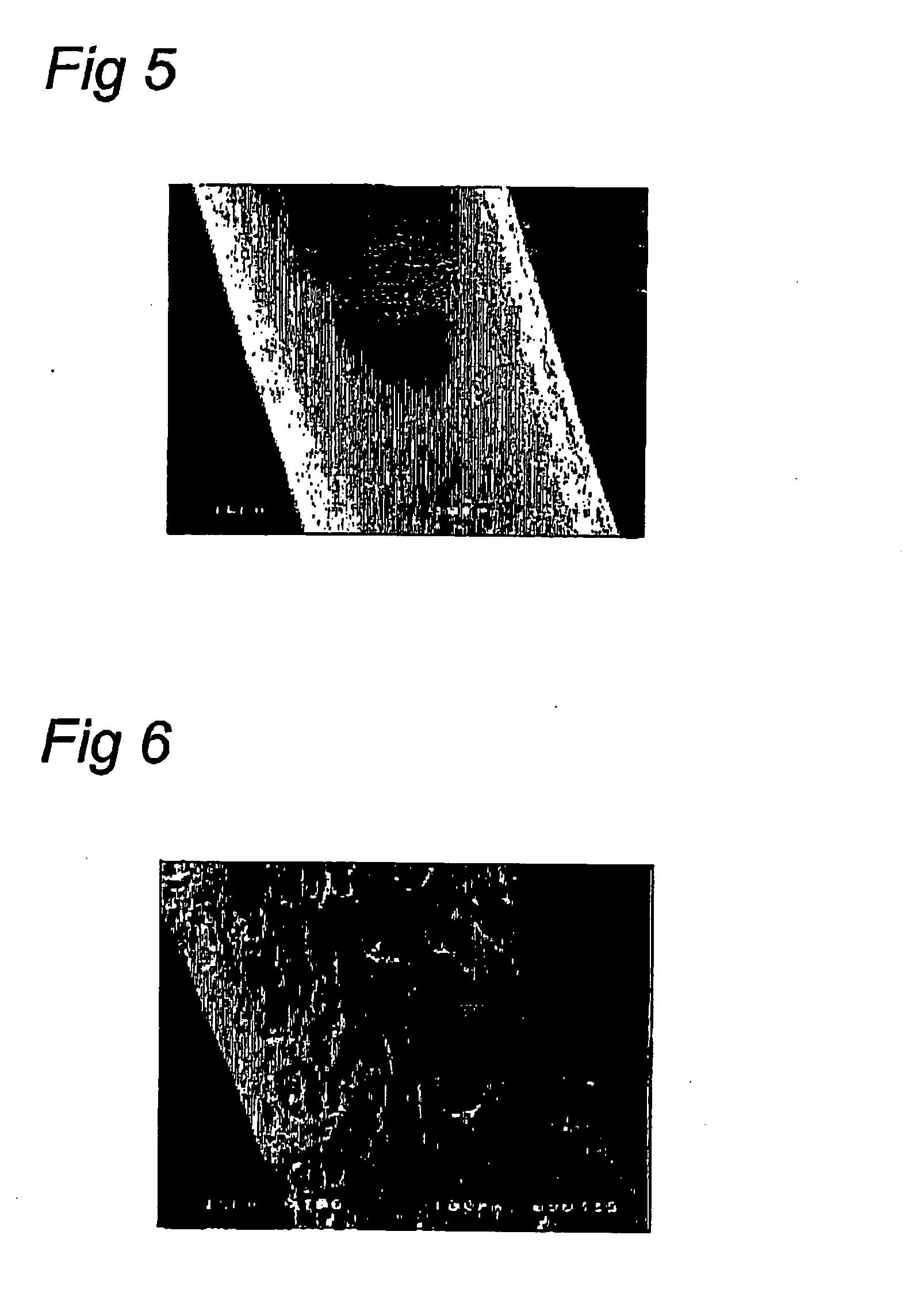
[0069] A polyethylene-vinyl-alcohol (EVAL with 44 % ethylene content) solid fibre was produced by dissolving 7 wt. % EVAL and 12 wt. % cation-exchange resin (CER) (Lewatit CNP 80 WS (Bayer), total ion-exchange capacity: 43 eq / l) and 7 wt. % octanol in dimethylsulfoxide (DMSO). The resin particles were smaller than 20 μm. The obtained dispersion was extruded through a tube-in-orifice spinneret (OD=2.4 and ID=1.65 mm) into a water bath (20° C.), where phase separation occurred. There was no bore liquid used for the production of solid fibre. This way a porous solid fibre was obtained with a particle load of 60 wt. % CER. The functional porous fibre was used for adsorption of bovine serum albumin (BSA) in a batch experiment. The functional porous fibres have an adsorption capacity of 165 mg BSA / g fibre. The BSA-modified functional porous fibre was consecutively treated with a glutaraldehyde (GA) soluti...


PUM

PropertyMeasurementUnit
temperatureaaaaaaaaaa
temperaturesaaaaaaaaaa

Abstract

The invention relates to a method for the preparation of porous polymeric fibres comprising functionalized or active particles. By extruding a mixture of one or more dissolved polymers with particulate material a porous fibre is obtained in which the particulate material is entrapped. Extrusion of the fibre occurs under two-step phase inversion conditions. In particular the porous fibres can be used for the isolation of macromolecules such as peptides, proteins, nucleic acids or other organic compounds from complex reaction mixtures, in particular from fermentation broths. Another application is the immobilization of a catalyst in a reaction mixture.

Description

FIELD OF THE INVENTION [0001] The present invention relates to a method for the preparation of porous polymeric fibres comprising functionalised or active particles, in particular comprising particles that are still accessible and active after preparation, and to the porous polymeric fibres thus obtained. Also the invention relates to the use of such fibres as means of purification and / or isolation of a component from a (complex) mixture, like for instance fermentation broths or as catalyst in reaction mixtures. For such use preferably the porous polymeric fibres are comprised in modules such as described hereinbelow. BACKGROUND OF THE INVENTION [0002] Porous polymeric matrices comprising particles have been described before. [0003] For instance in U.S. Pat. No. 6,048,457 cast porous polysulfone membrane structures comprising sorptive particles such as active carbon, (fumed or derivatised) silica or (functionalised) polystyrenedivinylbenzene beads are described. It concerns cast-in-...

Claims


Application Information

Patent Timeline
Patent Type & Authority Applications(United States)
IPC IPC(8): D02G3/00B01D15/08B01D15/32B01D15/34B01D67/00B01D69/08B01D69/14B01J20/28B01J20/281B01J31/08B01J31/10B01J35/06B01J47/00C12N11/04C12N11/08D01D5/247D01F1/02D01F1/10
CPCB01D15/325Y10T428/2929B01D67/0018B01D69/08B01D69/141B01J20/20B01J20/28023B01J20/28028B01J31/06B01J31/068B01J31/08B01J31/10B01J35/06B01J47/007C12N11/04C12N11/08D01D5/247D01F1/10B01D2323/22B01D2325/10B01D2325/12B01D2325/42Y10T428/2913B01D15/34
Inventor KOOPS, GEERT-HENDRIKAVRAMESCU, MARIA ELENABORNEMAN, ZANDRIEKIYONO, RYOTAROWESSLING, MATTHIAS
Owner NEOKIDNEY HLDG
Why Eureka
Try Eureka