Luminescence device, display apparatus and metal coordination compound

a technology of metal coordination compound and luminescence device, which is applied in the direction of discharge tube luminescnet screen, natural mineral layered products, etc., can solve the problems of luminescent deterioration, lowering the resultant luminescence efficiency especially at a higher current density, and it is difficult to expect the resultant el characteristics of phosphorescent materials

Inactive Publication Date: 2002-05-30
CANON KK
View PDF0 Cites 180 Cited by
  • Summary
  • Abstract
  • Description
  • Claims
  • Application Information

AI Technical Summary

Problems solved by technology

However, the above-mentioned organic EL devices utilizing phosphorescence have accompanied with a problem of luminescent deterioration particularly in an energized state.
This is because the longer phosphorescence life increases molecules placed in their triplet excited state which is a waiting state for phosphorescence, thus lowering the resultant luminescence efficiency particularly at a higher current density.
Accordingly, different from the fluorescent material, it is generally difficult to expect the resultant EL characteristics for the phosphorescent material by simply removing a part of characteristics from photoluminescence results.
This is because the longer phosphorescence life increases molecules placed in their triplet excited state which is a waiting state for phosphorescence, thus lowering the resultant luminescence efficiency particularly at a higher current density.

Method used


Image

  • Luminescence device, display apparatus and metal coordination compound
  • Luminescence device, display apparatus and metal coordination compound
  • Luminescence device, display apparatus and metal coordination compound

Examples


examples i-11-i-13

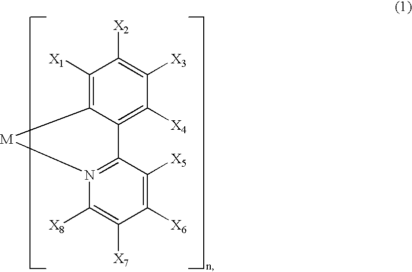
[0135] In these examples, metal coordination compounds of formula (1) (Ex. Comp. Nos. (I-1), (I-32) and (I-49) were used in respective luminescence layers for Examples I-11-I-13, respectively.

[0136] Each of luminescence devices having a structure shown in FIG. 1C were prepared in the following manner.

[0137] On a glass substrate (transparent substrate 15), a 100 nm-thick film (transparent electrode 14) of ITO (indium tin oxide) was formed by sputtering, followed by patterning to have an (opposing) electrode area of 3 mm.sup.2.

[0138] On the ITO-formed substrate, three organic layers and two metal electrode layers shown below were successively formed by vacuum (vapor) deposition using resistance heating in a vacuum chamber (10.sup.-4 Pa).

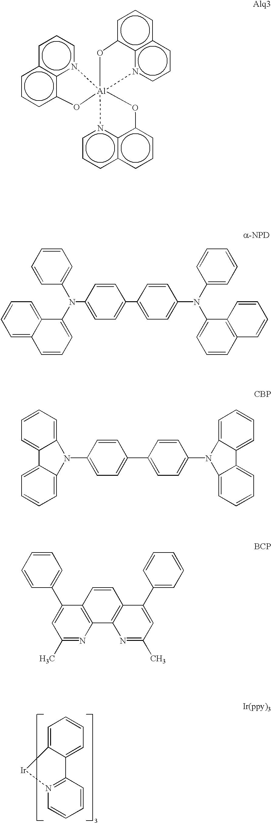
[0139] Organic layer 1 (hole transport layer 13) (40 nm): .alpha.-NPD

[0140] Organic layer 2 (luminescence layer 12) (20 nm): mixture of CBP: metal coordination compound of formula (1) (93:7 by weight)

[0141] Organic layer 3 (exciton diffusion prevention...

example i-14

(Synthesis of Ex. Comp. No. (I-1))

[0159] 15

[0160] In a 1 liter-three necked flask, 20.0 g (126.6 mM) of 2-bromopyridine, 17.7 g (126.4 mM) of 3-fluorophenylbronic acid, 130 ml of toluene, 65 ml of ethanol and 130 ml of 2M-sodium carbonate aqueous solution were placed and stirred in a nitrogen gas stream at room temperature. Under stirring, to the mixture, 4.60 g (3.98 mM) of tetrakis (triphenyl-phosphine) palladium (0) was added, followed by heat-refluxing for 6 hours under stirring in nitrogen gas stream.

[0161] After the reaction, the reaction mixture was cooled, followed by extraction with cool water and toluene. The organic layer was washed with water until the system showed neutral, followed by distilling off of the solvent under reduced pressure to obtain a residue. The residue was purified by silica gel column chromatography (eluent: toluene / ethyl acetate=5 / 1) to obtain 6.0 g of 2-(3-fluorophenyl)pyridine (pale brown liquid) (Yield: 34.6%). 16

[0162] In a 100 ml-four necked fla...

example i-15

(Synthesis of Ex. Comp. No. (I-32))

[0164] 17

[0165] In a 1 liter-three necked flask, 20.8 g (131.6 mM) of 2-bromopyridine, 25.0 g (131.6 mM) of 3-trifluoromethylphenylbronic acid, 130 ml of toluene, 65 ml of ethanol and 130 ml of 2M-sodium carbonate aqueous solution were placed and stirred in a nitrogen gas stream at room temperature. Under stirring, to the mixture, 4.76 g (4.12 mM) of tetrakis (triphenyl-phosphine) palladium (0) was added, followed by heat-refluxing for 7 hours under stirring in nitrogen gas stream.

[0166] After the reaction, the reaction mixture was cooled, followed by extraction with cool water and toluene. The organic layer was washed with water until the system showed neutral, followed by distilling off of the solvent under reduced pressure to obtain a residue (pale brown liquid). The residue was purified by silica gel column chromatography (eluent: toluene / hexane=1 / 1) to obtain 6.0 g of 2-(3-trifluoromethylphenyl)pyridin-e (pale brown liquid) (Yield: 21.1%). 18

[...


PUM

PropertyMeasurementUnit
peak emission wavelengthaaaaaaaaaa
thicknessaaaaaaaaaa
brightnessaaaaaaaaaa

Abstract

A luminescence device is principally constituted by a pair of electrodes and an organic compound layer disposed therebetween. The layer contains a metal coordination compound represented by the following formula (1): wherein M denotes Ir, Rh or Pd; n is 2 or 3; and X1 to X8 independently denote hydrogen atom or a substituent selected from the group consisting of halogen atom; nitro group; trifluoromethyl group trialkylsilyl group having three linear or branched alkyl groups each independently having 1-8 carbon atoms; and a linear or branched alkyl group having 2-20 carbon atoms capable of including one or at least two non-neighboring methylene groups which can be replaced with -O-, -S-, -CO-, -CO-O-, -O-CO-, -CH=CH- or -C=C- and capable of including hydrogen atom which can be replaced with fluorine atom; with the proviso that at least one of X1 to X8 is a substituent other than hydrogen atom, and X2 and X3 cannot be fluorine atom at the same time.

Description

FIELD OF THE INVENTION AND RELATED ART[0001] The present invention relates to a luminescence device, a metal coordination compound therefor and a display apparatus including the luminescence device. More specifically, the present invention relates to an organic (electro-)luminescence device employing a metal coordination compound having a formula (1) or (2) appearing hereinafter as a luminescence material, the metal coordination compound adapted for use in the luminescence device, and a display apparatus using the luminescence device.[0002] An organic electroluminescence (EL) device has been extensively studied as a luminescence device with a high responsiveness and high efficiency.[0003] The organic EL device generally has a sectional structure as shown in FIG. 1A or 1B (e.g., as described in "Macromol. Symp.", 125, pp. 1-48 (1997)).[0004] Referring to the figures, the EL device generally has a structure including a transparent substrate 15, a transparent electrode 14 disposed on t...

Claims


Application Information

Patent Timeline
Patent Type & Authority Applications(United States)
IPC IPC(8): H01L51/50C07D213/02C07D213/61C07D213/65C07F7/08C07F15/00C07F19/00C09K11/06H01L51/00H01L51/30H05B33/12H05B33/14
CPCC07F15/0033Y10S428/917C07F15/0086C09K11/06C09K2211/1003C09K2211/1011C09K2211/1029C09K2211/185H01L51/0052H01L51/0059H01L51/0062H01L51/0081H01L51/0084H01L51/0085H01L51/0087H01L51/5012H01L51/5016H05B33/14C07F15/006H10K85/649H10K85/615H10K85/631H10K85/324H10K85/341H10K85/342H10K85/346H10K50/11H10K2101/10
Inventor TAKIGUCHI, TAKAOTSUBOYAMA, AKIRAMIZUTANI, HIDEMASAOKADA, SHINJIROMIURA, SEISHIMORIYAMA, TAKASHIIGAWA, SATOSHIKAMATANI, JUNFURUGORI, MANABU
Owner CANON KK
Why Eureka
Try Eureka