Exhaust gas recirculation

a technology of exhaust gas and recirculation, which is applied in the direction of electrical control, engine operation, and addition of non-fuel substances to fuel, can solve problems such as engine damage, and achieve the effect of reducing compression ratio and increasing operating regim

Inactive Publication Date: 2006-05-18
MAHLE POWERTRAIN
View PDF7 Cites 24 Cited by
  • Summary
  • Abstract
  • Description
  • Claims
  • Application Information

AI Technical Summary

Benefits of technology

[0007] It has been found, unexpectedly, that the use of both internal and external EGR increases the operating regime in which controlled auto ignition can be used in both steady state and transient conditions by a substantial amount, with a lower compression ratio than required for homogenous charge compression ignition (‘HCCI’) and without the inlet air heating required by HCCI

Problems solved by technology

Outside these regimes, insufficient burst gas temperatures or the onset and increase of engine knock, which is associated with unwanted engine noise and can ultimately result in engine damage, becomes unacceptable and a transition to spark ignition operation is required.

Method used


Image

  • Exhaust gas recirculation
  • Exhaust gas recirculation
  • Exhaust gas recirculation

Examples


Embodiment Construction

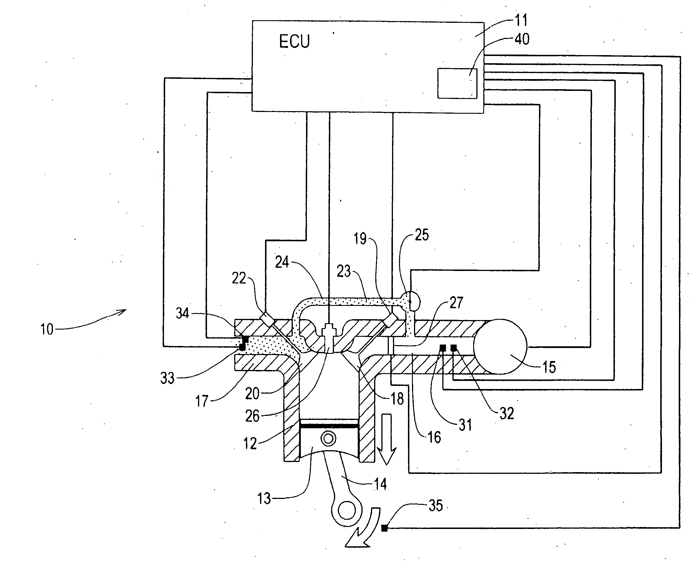
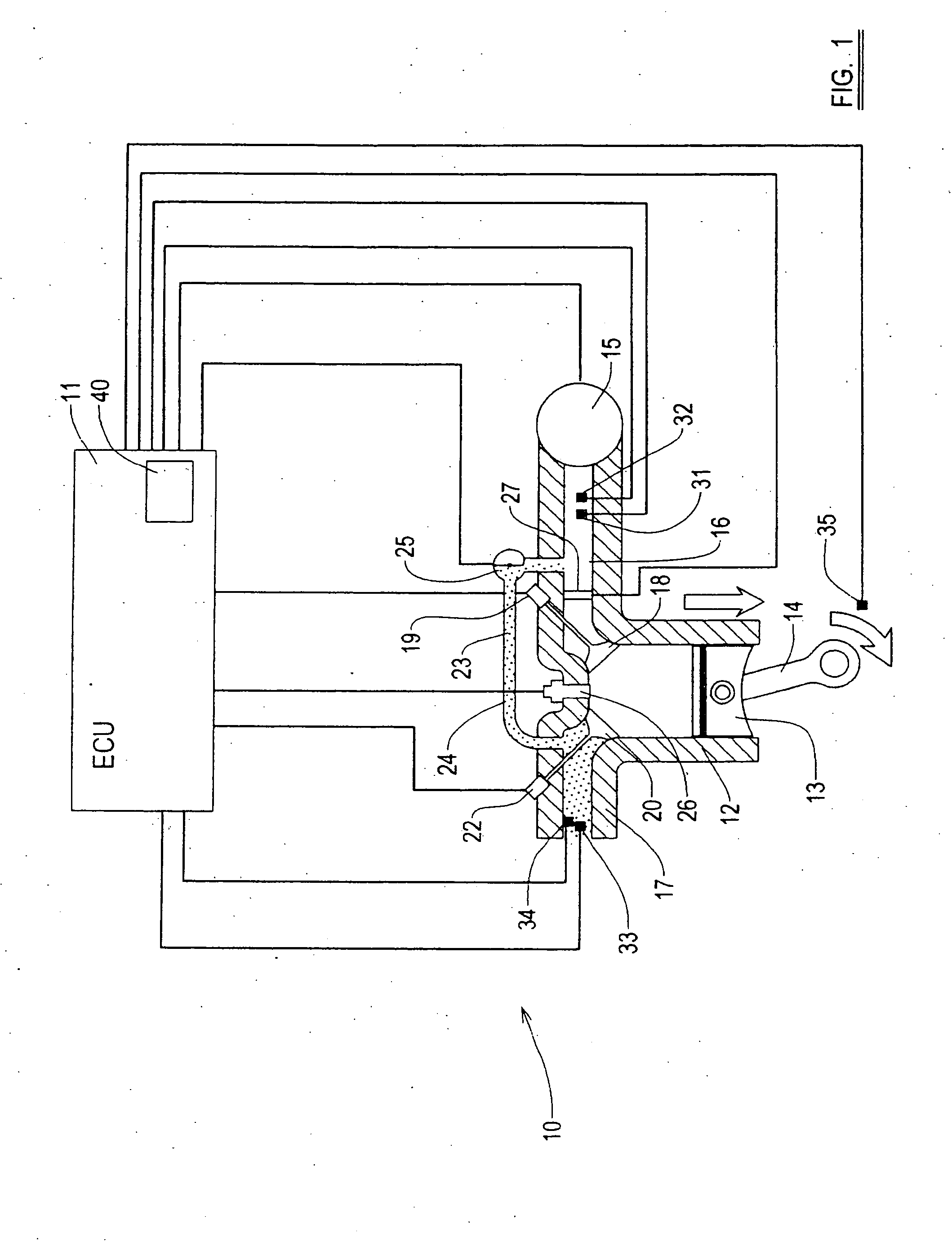
[0038] Referring now to FIG. 1, part of an internal combustion engine embodying the present invention is shown at FIG. 1. The invention comprises an engine management system having an electronic control unit 11 and one or a plurality of cylinders, of which for clarity only one is shown at 12. In conventional manner, a piston 13 is moveable within the cylinder 12 and drives a crank shaft through a con rod 14. Air is supplied to the cylinder 12 through an intake throttle 15 and manifold generally illustrated at 16. Fuel may be introduced into the air in the manifold 16 or in the cylinder 12, depending on whether indirect or direct injection is used. The ECU 11 is preferably operable to control the supply of fuel to provide the desired air-to-fuel ratio λ for the engine operating conditions. Exhaust gases from the combustion are released from the cylinder via an outlet 17. A fresh charge, i.e. air or a fuel / air mix, is admitted to the cylinder 12 through an inlet port 18 and controlled...


PUM


Abstract

An internal combustion engine comprising, an engine management unit, a combustion chamber having an inlet port and an outlet port, a fuel supply mechanism to supply gasoline to the engine, a valve train mechanism to permit introduction of air to the inlet port of the combustion chamber and release exhaust gases from the outlet port of the combustion chamber, and an external recirculating system whereby exhaust gases from the outlet port may be passed to the inlet port, wherein, the engine management unit is operable to, control the valve train mechanism to retain and / or rebreathe exhaust gases within the combustion chamber to cause the engine to operate in a controlled auto ignition combustion mode, and control the external recycling system to supply exhaust gases to the inlet port in the controlled auto ignition combustion mode, such that self-ignition occurs in the combustion chamber.

Description

FIELD OF THE INVENTION [0001] This invention relates to control of an internal combustion engine, in particular a combustion engine operating in a controlled auto ignition mode. BACKGROUND OF THE INVENTION [0002] Conventionally, internal combustion engines use “spark ignition” (“SI”) to ignite a fuel-air mixture in the engine cylinder using an electrical spark. A further operating mode is also known, referred to as controlled auto-ignition (“CAI”), for example as described in Allen J., and Law D.,: “Variable Valve Actuated Controlled Auto-Ignition; Speed Load Maps and Strategic Regimes of Operation”, SAE paper no. 2002-01-0422. In CAI, hot exhaust gases from combustion are either retained in the engine cylinder or rebreathed from the exhaust manifold, so-called exhaust gas recirculation (“EGR”) for example by controlling the cylinder valves such that the exhaust valve is closed early or re-opened during the inlet stroke of the engine cycle to increase the trapped burnt gases. The mi...

Claims


Application Information

Patent Timeline
Patent Type & Authority Applications(United States)
IPC IPC(8): F02M25/07F01L1/34F02D41/04F02D41/00F02D41/30
CPCF02B1/12F02D41/0002F02D41/006F02D41/0065F02D41/1446F02D41/1454F02D41/187F02D41/3035F02D41/3041F02D2041/001F02D2041/0015F02D2200/0406F02D2200/0414Y02T10/42Y02T10/47Y02T10/40F02D21/08F02D43/00
Inventor CAIRNS, ALASDAIRBLAXILL, HUGH
Owner MAHLE POWERTRAIN
Why Eureka
Try Eureka