Pneumatic method and apparatus for nano imprint lithography

a technology of imprint lithography and pneumatic method, which is applied in the field of pneumatic method and apparatus for nano imprint lithography, can solve the problems of template and/or workpiece deformation under mechanical pressure, further constraints on printing nanometer-scale features, and silicon wafers are typically not perfectly flat, so as to achieve high dimensional fidelity, avoid expensive mechanical tolerances, and flat all surfaces

Inactive Publication Date: 2006-05-18
GLOBALFOUNDRIES INC
View PDF9 Cites 18 Cited by
  • Summary
  • Abstract
  • Description
  • Claims
  • Application Information

AI Technical Summary

Benefits of technology

[0025] Other advantages of the present invention include that expensive mechanical tolerances can be avoided in obtaining flatness of all surfaces.
[0026] Further, high dimensional fidelity can be maintained in the lateral directions (in the plane of the pattern).

Problems solved by technology

The deformation of the template and / or workpiece under applied mechanical pressure is a problem when the features of the template are of very small (e.g., nanometer) dimensions and for which it is desirable to maintain long range dimensional tolerances on this scale.
Additionally, imperfections with respect to flatness (e.g., uniform thickness) of either the template or workpiece impose further constraints to printing nanometer-scale features.
Thus, the silicon wafers typically are not perfectly flat.
This is problematic.
More specifically, there has been no apparatus or method in which pneumatic pressure is uniformly applied against either (or both) the quartz template and the workpiece to achieve uniform compression of the photoresist.
Hence, such methods have not been able to retain the essential transparent properties of the quartz template while applying uniform pressure to a conformal membrane, thereby allowing the compensation for planarity defects in both template and workpiece.
These methods have several major drawbacks, including that dimensional integrity in the plane of the template is not sufficiently preserved.
Additionally, the motion of the polymer material due to non-uniform pressure or due to small temperature gradients generate distortions to the printed patterns that prohibit their use in microelectronic lithography.
While thermal curing is an option, there has been no conventional method which has adequately addressed the case (and the attendant problems) where the polymer is cured by exposure to ultraviolet light (UV).
Additionally, ultraviolet (UV) transparency is severely degraded by the polymer material.
Further, exposure to UV radiation degrades the polymer material over time.

Method used


Image

  • Pneumatic method and apparatus for nano imprint lithography
  • Pneumatic method and apparatus for nano imprint lithography
  • Pneumatic method and apparatus for nano imprint lithography

Examples


second embodiment

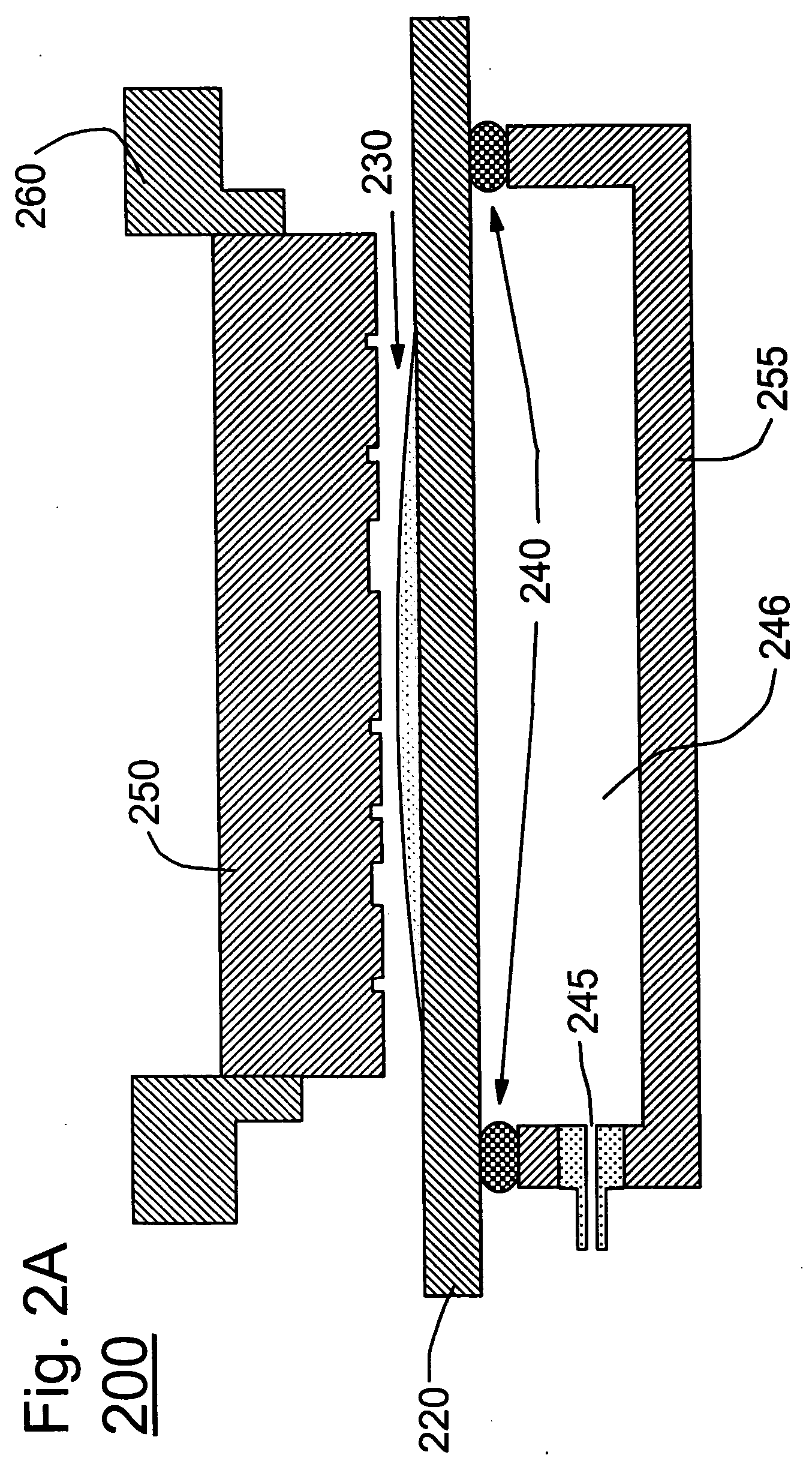
[0049] For example, FIG. 2A illustrates a pneumatic membrane imprint lithography apparatus 200 according to the present invention, in which pressure is applied to the backside of a flexible workpiece 220 (e.g., a silicon wafer). The workpiece has a photoresist 230 formed thereon.

[0050] The apparatus 200 uses a transparent window 250 with an etch pattern (mold) thereon as the lithographic pattern template. The transparent window is mounted to a mounting flange 260, and is opposed to the flexible workpiece 220.

[0051] The window 250 is preferably formed of a material chosen to be transparent to the radiation (e.g., actinic wavelengths) necessary to expose / activate the photoresist 230, but also, generally, transparent to visible wavelengths so that optical alignment can be performed of the pattern on the mask with the underlying workpiece 220. That is, the user should be able to look (image) through the window 250 in the alignment process.

[0052] The workpiece 220 may be held (or conta...

first embodiment

[0053] The rubber seal 240 is coupled to a housing structure 255 which includes an air pressure inlet 245 for receiving an air pressure from a pneumatic pressure source. Instead of air, as in the first embodiment, any gas may be used such as nitrogen, helium or the like. The inlet may have a diameter that is small, since the amount of gas flow is small.

[0054] As shown, the structure of the rubber seal 240 / housing 255 forms a predetermined gap 246 which is formed between a lower surface of the workpiece 220 and the interior surface of the housing 255.

[0055] As before, the window 250 is preferably optically perfect and preferably is formed of flat quartz material or the like.

[0056] The gap 246 preferably has a thickness within millimeter range but as would be evident the thickness of the gap depends upon the designer's constraints and requirements such as the composition (e.g., material and thickness) of the membrane and the amount of pressure being input to the gap to make the memb...

third embodiment

[0060] Additionally, FIG. 2B illustrates a pneumatic membrane imprint lithography apparatus 290 according to the present invention using partial vacuum and atmospheric pressure.

[0061] Specifically, the apparatus 290 is somewhat similar to that shown in FIG. 2A, but includes a mounting flange 291 having air conduits 292 formed therein. The air conduits 292 are coupled to a vacuum connection 293 via an inlet 245. An atmospheric pressure 294 is applied against the backside of the flexible workpiece 220. A partial vacuum 295 exists between the window 250 and the photoresist 230.

[0062] It is noted that in all three exemplary cases, it is intended that the workpiece can be positioned relative to the template so as to be able to print multiple impressions of the template on the workpiece in different locations (i.e., print a stepped pattern such as chip patterns on a semiconductor wafer).

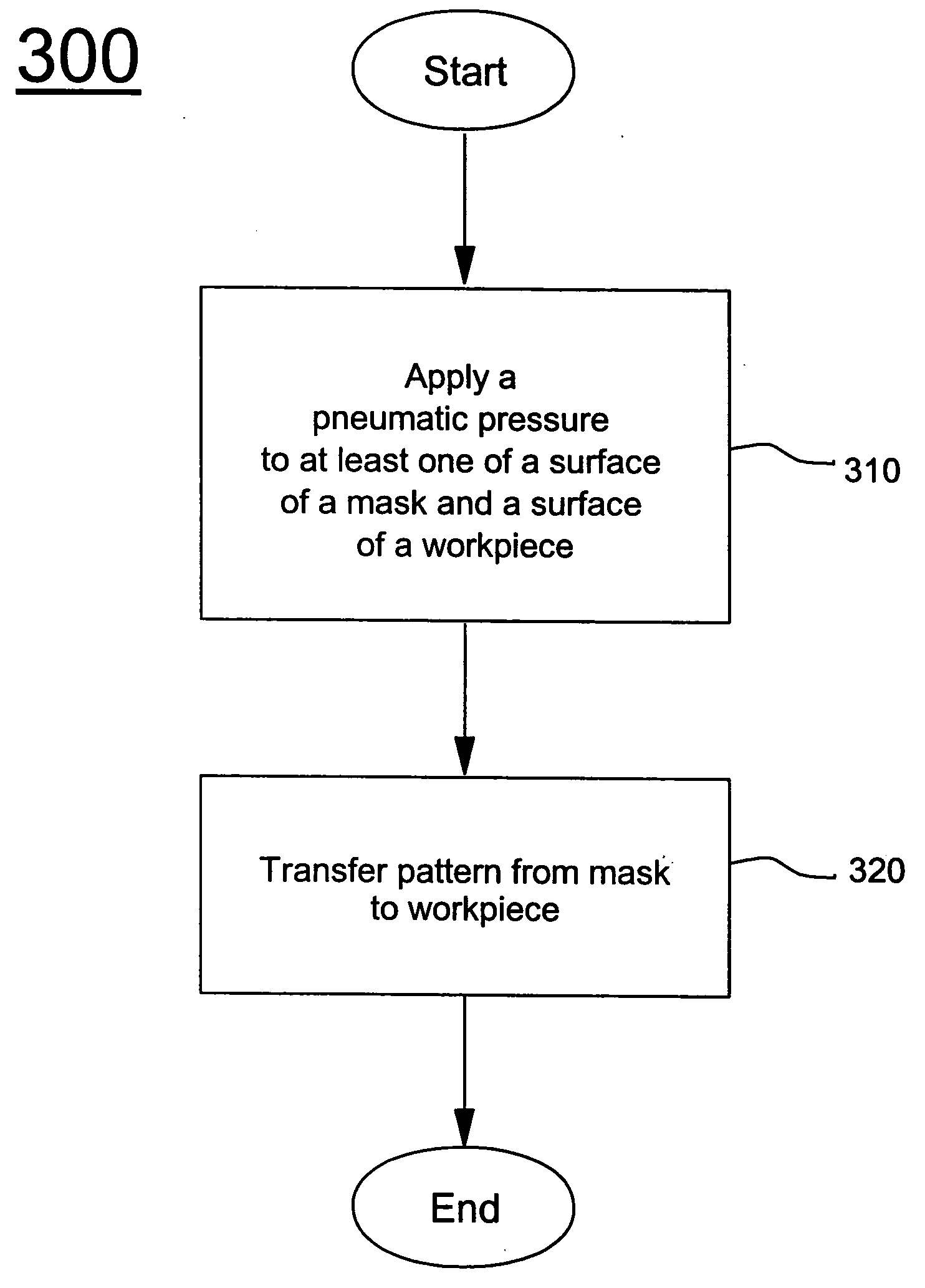
[0063] Turning to FIG. 3, a flowchart of the inventive method 300 of nano lithography is shown.

[0064...


PUM

PropertyMeasurementUnit
thicknessaaaaaaaaaa
surface roughnessaaaaaaaaaa
pressureaaaaaaaaaa

Abstract

A method (and apparatus) for nano lithography, includes applying a pneumatic pressure to at least one of a surface of a semi-rigid mask or template and a portion of a surface of a resist-coated workpiece, and, by the applying of the pneumatic pressure, transferring a pattern from the mask to the workpiece.

Description

BACKGROUND OF THE INVENTION [0001] 1. Field of the Invention [0002] The present invention generally relates to a method and apparatus for nano imprint lithography, and more particularly to a pneumatic method and apparatus for nano imprint lithography. [0003] 2. Description of the Related Art [0004] The process of imprint lithography involves pressing a template (or mold or mask) against a polymer or photoresist-coated workpiece, curing the polymer and removing the template from the workpiece leaving behind an impression of the template in the cured polymer coating. The deformation of the template and / or workpiece under applied mechanical pressure is a problem when the features of the template are of very small (e.g., nanometer) dimensions and for which it is desirable to maintain long range dimensional tolerances on this scale. [0005] Additionally, imperfections with respect to flatness (e.g., uniform thickness) of either the template or workpiece impose further constraints to print...

Claims


Application Information

Patent Timeline
Patent Type & Authority Applications(United States)
IPC IPC(8): B29C59/02B29C33/58B29C71/04H01L21/302H01L21/461
CPCB29C43/003B29C43/021B29C43/3642B29C2043/025B29C2043/3647B29C2043/3649B82Y10/00B82Y40/00G03F7/0002H01L21/0273
Inventor COLBURN, MATTHEW E.MARTIN, YVES C.VAN KESSEL, THEODORE G.WICKRAMASINGHE, HEMATHA K.
Owner GLOBALFOUNDRIES INC
Why Eureka
Try Eureka