Trenched MOSFETS with part of the device formed on a (110) crystal plane

a crystal plane and mosfet technology, applied in the direction of semiconductor devices, basic electric elements, electrical appliances, etc., can solve the problems of affecting the practical implementation of such configurations, affecting the mobility of channels, and difficult to achieve high interface state density

Inactive Publication Date: 2006-05-25
ALPHA & OMEGA SEMICON LTD
View PDF2 Cites 53 Cited by
  • Summary
  • Abstract
  • Description
  • Claims
  • Application Information

AI Technical Summary

Benefits of technology

[0012] It is therefore an object of the present invention to provide a new design and manufacturing methods and device configuration for the power MOSFET devices to take advantages of building the devices on planes of different crystal orientations such that the limitations of the conventional methods can be overcome.

Problems solved by technology

Even though the techniques to provide improved carrier mobility for a P-channel MOSFET, i.e., metal oxide silicon field effect transistors, by forming the transistor on a (110) crystal plane is known, the difficulties of high interface state density is still a limitation for practical implementation of such configurations.
The thicker oxidation thus results in a thick gate oxide layer and lead to an adversely affected higher threshold voltage.
Furthermore, measured data also provide some evidence that thicker oxide layer also causes a degradation of channel mobility.
Furthermore, even when there are several U.S. patents and patent applications that explored the techniques of building the MOS devices on a semiconductor substrate having a (110) crystal orientation, these disclosures are still limited by several technique difficulties due to different practical configuration and manufacture constraints due to the oxide layer thickness variations along different crystal orientations as will be discussed below.
Hasegawa disclose the benefits of building a p-channel MOSFET in a (110) crystal plane, however the configurations and method as disclosed would be too complicate and costly with limited merits for practical application to build a commercial MOSFET product.

Method used


Image

  • Trenched MOSFETS with part of the device formed on a (110) crystal plane
  • Trenched MOSFETS with part of the device formed on a (110) crystal plane
  • Trenched MOSFETS with part of the device formed on a (110) crystal plane

Examples


Embodiment Construction

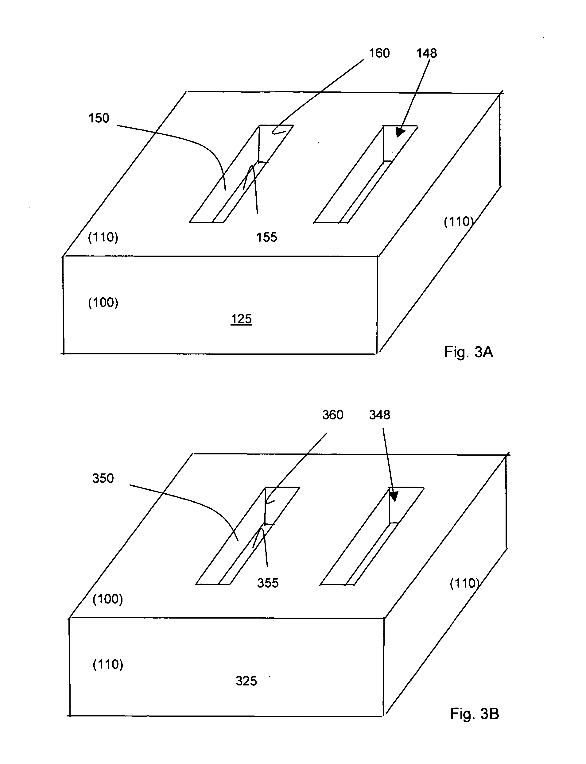
[0026] For P-channel implementations, FIGS. 3A and 3B show the orientations of the substrate and trench according to the current invention. In FIG. 3A, the silicon ingot 125 is grown in the (110) plane. The silicon ingot 125 provides a configuration that four sidewalls are situated with four sidewall surfaces forming a corner with a corner angle of 90 degrees, thus these sidewall surfaces are perpendicular to each other. Two of these sidewalls are along a (100) crystal orientation and two are along a (110) crystal orientation. Referring to FIG. 3A, two sidewalls 150 and bottom 155 of the trench 148 are formed along a (110) crystal orientation while the termination end surface 160 of the trench 148 is formed along a (100) crystal orientation. In FIG. 3B, the wafer 325 is formed by rotating a normal (100) wafer as shown in FIG. 2 by 45° thus forming two interface planes on a (110) plane while the top and bottom planes are still on the (100) plane. As can be observed from FIG. 3B, when...


PUM


Abstract

This invention discloses an improved MOSFET devices manufactured with a trenched gate by forming part of the trench on a (110) crystal orientation of a semiconductor substrate. The trench is covering with a dielectric oxide layer along the sidewalls and the bottom surface or the termination of the trench formed along different crystal orientations of the semiconductor substrate. Special manufacturing processes such as oxide annealing process, special mask or SOG processes are implemented to overcome the limitations of the non-uniform dielectric layer growth.

Description

BACKGROUND OF THE INVENTION [0001] 1. Field of the Invention [0002] The invention relates generally to the semiconductor power devices. More particularly, this invention relates to a novel and improved manufacture method and device configuration for a metal-oxide semiconductor field effect transistor (MOSFET) trenched power device manufactured with part of trench oriented on a (110) crystal plane of a silicon wafer. [0003] 2. Description of the Prior Art [0004] Even though the techniques to provide improved carrier mobility for a P-channel MOSFET, i.e., metal oxide silicon field effect transistors, by forming the transistor on a (110) crystal plane is known, the difficulties of high interface state density is still a limitation for practical implementation of such configurations. Specifically, Sze disclosed in “Physics of Semiconductor Devices” (Wiley-Interscience, 1969, pp. 16, pp. 473) and B. Goebel, D. Schumann, E. Bertagnolli disclosed in IEEE Trans. Electronics Devices, Vol. 48...

Claims


Application Information

Patent Timeline
Patent Type & Authority Applications(United States)
IPC IPC(8): H01L31/113
CPCH01L29/045H01L29/4236H01L29/66734H01L29/7813H01L24/33H01L2924/13091H01L2924/1306H01L2924/00H01L2924/181H01L2924/14H01L29/7811
Inventor BHALLA, ANUPLUI, SIK K.TAI, SUNG-SHAN
Owner ALPHA & OMEGA SEMICON LTD
Why Eureka
Try Eureka