Motor controller

Active Publication Date: 2006-05-25
MITSUBISHI ELECTRIC CORP
View PDF9 Cites 24 Cited by
  • Summary
  • Abstract
  • Description
  • Claims
  • Application Information

AI Technical Summary

Benefits of technology

[0009] According to the invention, the motor is made in a structure having the motor windings opened at both ends. The one end terminals of the phase windings are respectively connected to the output terminals of the first inverter circuit while the other end terminals are respectively connected to the output terminals of the second inverter circuit. During power genera

Problems solved by technology

There is a problem that the contactor for use in turning on-off a great current is expensive and moreover to be shortened in life by frequent on-off uses.

Method used


Image

  • Motor controller
  • Motor controller
  • Motor controller

Examples


Example

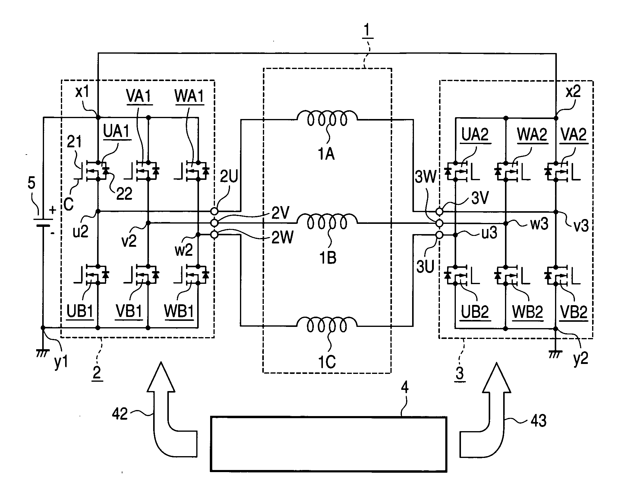
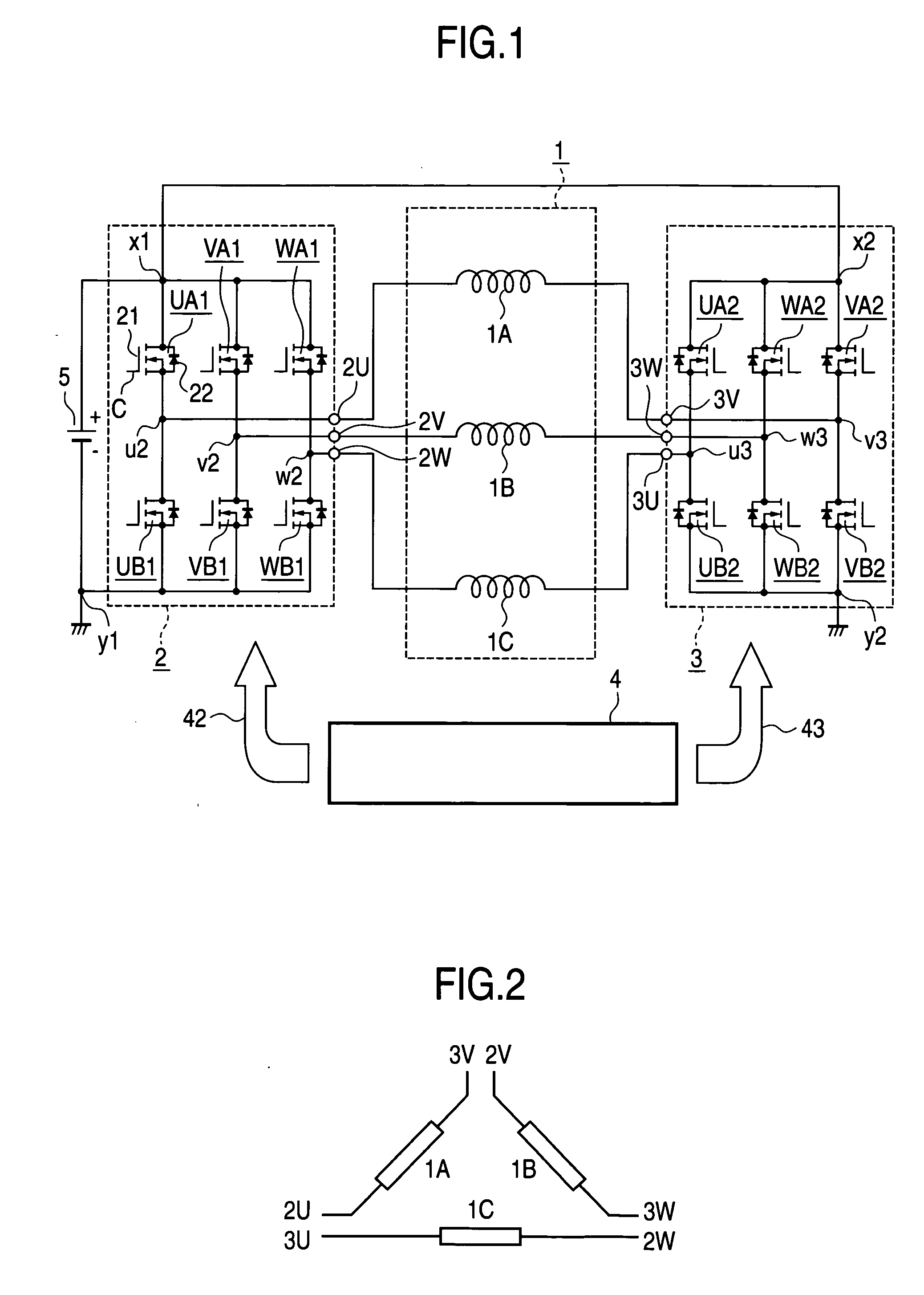
[0028]FIG. 1 shows a system configuration of a motor controller according to a first embodiment of the present invention. This system is configured as an electric motor generator having not only a function as an electric motor realizing so-called idle stop / start, say, automatically stopping the engine upon stopping the automobile and automatically operating it at a start thereof but also a function as the existing automotive alternator. The motor controller of the invention includes a motor 1 having stator windings 1A, 1B, 1C, inverter circuits 2, 3 for driving the motor 1, a control circuit 4 for forming a gate signal with which the two inverter circuits 2, 3 are controlled in operation, and a battery 5 which is a power source for driving the motor 1 and to which the generation energy is regenerated. The three-phase motor windings 1A, 1B, 1C are made opened at both ends, i.e. the both ends of the windings are extended out of the motor without providing a Δ-connection or a Y-connect...

Example

Second Embodiment

[0046]FIG. 12 shows a configuration of a motor controller according to a second embodiment of the invention. In the figure, like or corresponding elements are attached with like references. The difference from the first embodiment lies only in that a changeover switch 6 is inserted between a battery “+” side input terminal x2 of the switch block of an inverter circuit 3 and the “+” terminal of the battery 5. In the second embodiment, the changeover switch 6 is structured by a MOSFET.

[0047] The operation of the controller is now described separately upon powering and during power generation. First of all, a high voltage signal is inputted from the control circuit 4 to a control terminal of the changeover switch 6, to maintain the switch on. This state is similar in state to the first embodiment and hence omitted to explain because the operation is similar, wherein operation and effect is similar to that of the first embodiment.

[0048] The operation in power generat...

Example

Third Embodiment

[0053]FIG. 16 shows a configuration of a motor controller according to a third embodiment of the invention, wherein like or corresponding elements to those of FIG. 12 are attached with like references. This embodiment is effective for the case powering (idle starting) torque is required only in a low rotation range. The difference from the second embodiment lies only in that the inverter circuit 3 is replaced with a switch unit 7 wherein the signal for controlling it is a control signal 47 for the switch unit 7.

[0054] The switch unit 7 is configured with a parallel connection of three blocks (WA2 and WD7, VA2 and VD7) wherein a series connection of a semiconductor switch element UA2 having one control terminal and a diode UD7 is taken as one block. The semiconductor switch element UA2, WA2, VA2 is configured with a parallel connection of a MOSFET 71 and a diode 72 (true for other blocks). The diode 72 connected parallel may use a parasitic diode formed within the M...


PUM


Abstract

A motor controller is provided which can be reduced in the number of the wirings and power semiconductor devices required while maintaining the function equivalent to or higher than that of the motor controller adopting the existing winding changeover scheme, thereby realizing cost and size reduction and life increase. The motor is made in a structure having motor windings opened at both ends. The one end terminals of phase windings are respectively connected to the output terminals of a first inverter circuit while the other end terminals are respectively connected to the output terminals of a second inverter circuit. During power generation, any one of the inverter circuits is driven on all the phases by means of a same control pulse.

Description

BACKGROUND OF THE INVENTION [0001] 1. Field of the Invention [0002] This invention relates to motor controllers, and more particularly to a motor controller adopting a winding changeover scheme. [0003] 2. Description of the Related Art [0004] In the existing vehicular alternating-current motors, it is a practice to carry out a changeover control of the stator winding from a star connection (Y connection) to a triangular connection (Δ connection) in order to improve the vehicle performance in medium and high speed ranges. There is a disclosure, for example, in JP-A-61-73591 (FIGS. 1-3 and related explanations thereof), as a motor control method based on such a winding changeover scheme. Namely, when reaching a speed higher than the upper limit of a speed range the ratio of an inverter output voltage and an output frequency is kept constant, the stator windings are changed over from a star connection (Y connection) into a triangular connection (A connection), thereby increasing the ph...

Claims


Application Information

Patent Timeline
IPC IPC(8): H02P5/00H02P21/04H02P23/03H02P27/06H02P27/08
CPCH02P25/20H02P27/06
Inventor URAKABE, TAKAHIROYAMAMOTO, TSUNENOBUASAO, YOSHIHITO
Owner MITSUBISHI ELECTRIC CORP
Why Eureka
Try Eureka