[0016] Alternatively, the circuit components may include spaced-apart conductors which are electrically coupled to the signaling circuit to “close” the signaling circuit to permit current flow when exposed to a
body fluid and / or device contents by a wall breach. Alternatively, the circuit may be altered, enabled or otherwise modified by a sufficient flow of electrolytes to enable, interpret, disrupt, or modify a
signal emission. The circuit components may include spaced apart conductors which are coupled to the signaling circuit to detect a change in resistance,
capacitance, impedance, or
voltage. Since the breach could be small and intermittent as it starts, it can be difficult to detect as a flow but the cumulative
gain or loss of the electrolytes from the contents or surrounding body fluids could cause a change in the resistance,
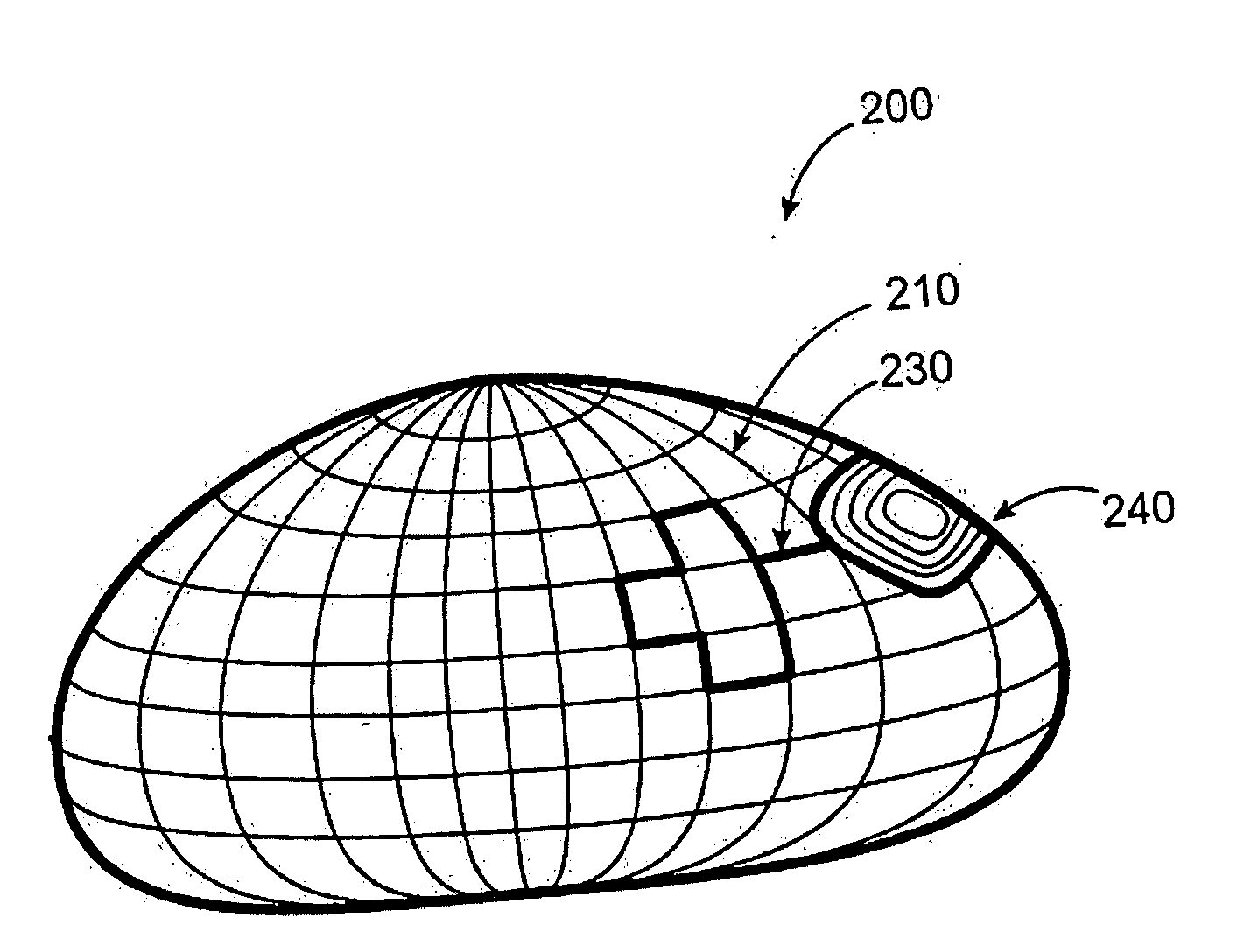
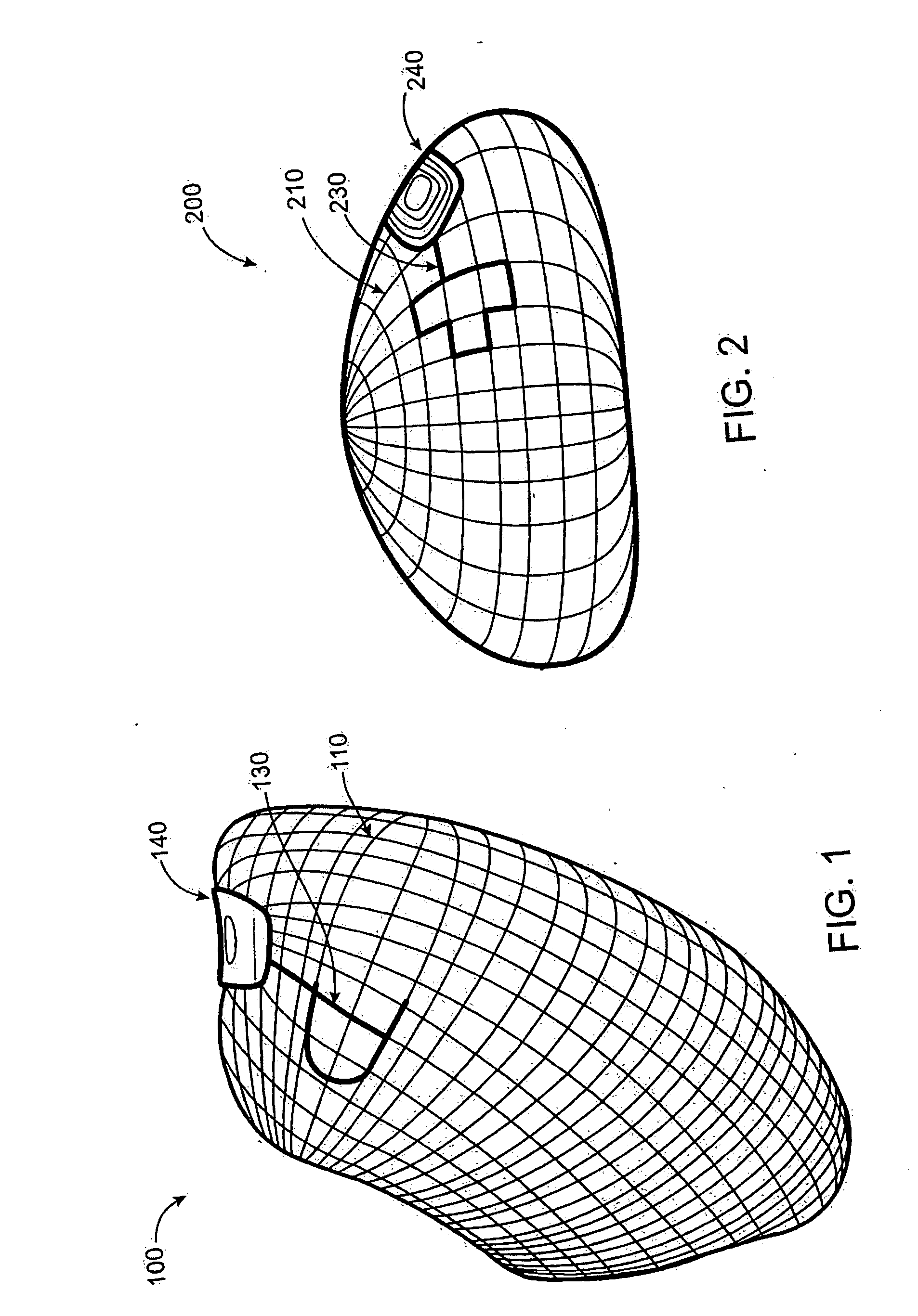
capacitance, or impedance across the conductors. Alternatively, the detection circuit is closed and the contact of the contents or the body fluids with the conductors could cause a break, disruption, or change in the functioning of the circuit. In the exemplary embodiments described below, the conductors may comprise meshes, films, or other relatively large surface areas covering most or all of the wall so that breach at any point in the wall will provide the intended
electrically conductive bridging between the conductors. The
coupling of the conductors may also cause, alter, or enable a
signal emission to alert the patient of the breach or potential breach. The spaced-apart conductors can have any one of a variety of shapes or configurations, continuous configurations, such as plates and films, or discontinuous configurations, such as lattices, meshes, and the like, can be placed in various locations, preferably near interior portions of the device where body fluids will
pool to enhance sensitivity and reliability of the detection.
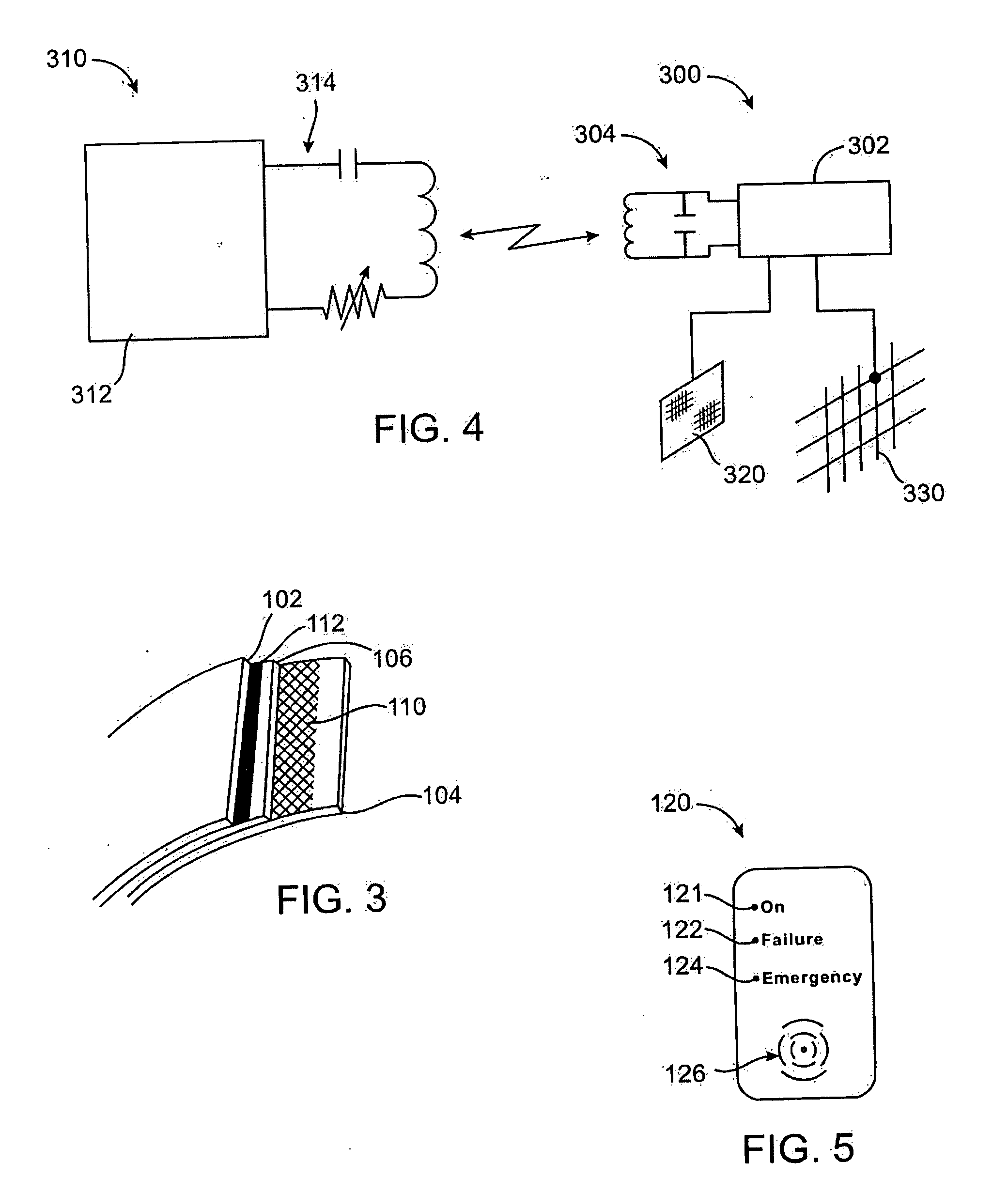
[0018] The signaling circuit can be active or passive. In a preferred embodiment, the signaling circuit will comprise a passive
transponder and antenna which are adapted to be powered and interrogated by an external reader. Such
transponder circuitry may conveniently be provided by using common radiofrequency identification (RFID) circuitry where the
transponder and tuned antenna are disposed on or within a
protected area in the
prosthesis and connected to remaining portions of the signaling circuit. Passively powered circuitry is particularly preferred in devices with
on board batteries where the amount of energy stored in the battery generally determines the functional product life. The antenna and transponder could be located in close proximity to the detection circuitry or placed elsewhere in the device or another part of the body. For example, by connecting the transponder circuitry to “open” conductors which is closed in the presence of body fluids and / or inflation medium, the signal emitted by the transponder upon interrogation by an external reader may be altered. Thus, the patient or medical professional may interrogate the
prosthesis and determine whether or not the
prosthesis remains intact or the
threat of an impending breach exists. This is a particularly preferred approach since it allows the user to determine that the transponder circuitry is functional even when a breach has not occurred.
[0024] Compromise of the device typically starts with a somewhat linear split or tear in surface of the device wall or covering from mechanical fatigue or handling damage. As the split propagates, it will
expose more and more lines of the lattice or area of the film to the body fluids and or device contents. Consequently, as the size and seriousness of the breach increases, the probability of detection increases. Embedding the detection material in the covering such as the wall of the
balloon further enables detection before a full breach of the entire thickness of the device wall.
[0026] The
transmitter can be a simple
wireless signal generator triggered by an
electric current or preferably a transponder using the well-established RFID technology, i.e., produces a
wireless signal when triggered by an interrogating signal. The
electric charge generated or the
electric current enabled by the probe in contact with the body fluids or device contents changes the
logic state thereby enabling the
transmitter to emit or causes it to emit a
wireless signal. Typically, the transponder is powered by the interrogating
radio frequency signal so that no power source of its own is required. Alternatively, the
transmitter could be powered by a micro battery or by the electrical power generated by a
chemical reaction. For protection from degradation by an acidic and
electrolyte solution and become potentially toxic, the transmitter or transponder circuit is encased in a highly resistant material, such as
silicone rubber or stainless steel. The transmitter or transponder circuit can be placed on the exterior, embedded in the wall, or preferably in the interior of the device for shielding from chemical degradation and mechanical stress. It can be placed in any orientation, preferably in the plane where the antenna is most sensitive and the transmitter is most effective in sending and receiving signals through
body tissue overlying the device.

