Method to increase low-energy beam current in irradiation system with ion beam

a technology of ion beam and beam current, which is applied in the field of improving the irradiation system with an ion beam, can solve the problems of reducing the yield of the most advanced devices, increasing the variation of device performance, and changing the basic device structure, so as to achieve the effect of increasing the low-energy beam curren

Inactive Publication Date: 2006-06-01
SENCORP
View PDF9 Cites 22 Cited by
  • Summary
  • Abstract
  • Description
  • Claims
  • Application Information

AI Technical Summary

Benefits of technology

[0069] According to a ninth aspect of this invention, a mass analysis slit is provided on a downstream side of the mass analysis device. The mass analysis slit is integrally composed of three slits including a slit for normal implantation, a slit for high mass-resolution low-dose implantation, and a slit with a narrow opening for beam centering and the three slits are switchable therebetween depending on the normal implantation, the high mass-resolution low-dose implantation, and the beam centering before implantation. The beam transformer comprises a vertically focusing DC quadrupole electromagnet QD and a horizontally focusing DC quadrupole electromagnet QF. The vertically focusing DC quadrupole electromagnet QD and the horizontally focusing DC quadrupole electromagnet QF transform a beam having a circular cross-section or an elliptical or oval cross-section to the beam having an elliptical or oval cross-section that is long in a scan direction in all the region of the beam line after deflection for scanning, thereby increasing the low-energy beam current.

Problems solved by technology

This increases variation in device performance and extremely lowers yield of the most advanced devices.
However, if the beam divergence angle is too large, distribution of dopants in a lateral direction is increased so that the size of a basic device structure become different from designed and therefore the device performance is degraded.
However, there is no flexibility in implantation angle (tilt angle).
Although it is possible to manufacture a disk with a small implantation angle deviation, as another solution for item (3), the wafer cooling performance of such a disk necessarily becomes insufficient.
Therefore, in the batch high-current ion implantation system, it is impossible to enhance the accuracy of implantation angle without degrading the current performance of the system.
(A) It is not possible to carry out ion implantation at a large implantation angle exceeding 7°.
(B) Following high-speed rotation of the disk with the wafers mounted thereon, there is a possibility that a structure of the surface of each wafer is damaged due to particles moving on the wafer.
However, it can no longer be used as the high-current ion implantation system that is required to have high accuracy for coping with the device shrinkage.
However, the ion implantation system of the first example has the following defects.
It is quite difficult to achieve a beam density non-uniformity of 1% or less.
Particularly at low energy, the beam diverges naturally due to the space-charge effect and therefore it is almost impossible to control the beam density.
Such beam ions become energy contamination.
Further, since such beam ions are not measured as beam current, there also occurs an error in dose (overdose).
After all, like the foregoing batch ion implantation system, the ribbon beam type single-wafer high-current ion implantation system is high in productivity because its beam current is large, but poor in implantation accuracy.
However, the ion implantation system of the second example has the following defects.
After all, the two-dimensional mechanical scan type high-current ion implantation system is low in productivity and also not good in implantation angle accuracy.
However, the ion implantation system of the third example has the following defects.
Particularly at extremely low energy, the beam can hardly be transported.
After all, the beam scan type middle-current ion implantation system enables highly accurate implantation but cannot transport to the wafer a beam current high enough for use in the high-current ion implantation process.

Method used


Image

  • Method to increase low-energy beam current in irradiation system with ion beam
  • Method to increase low-energy beam current in irradiation system with ion beam
  • Method to increase low-energy beam current in irradiation system with ion beam

Examples


Embodiment Construction

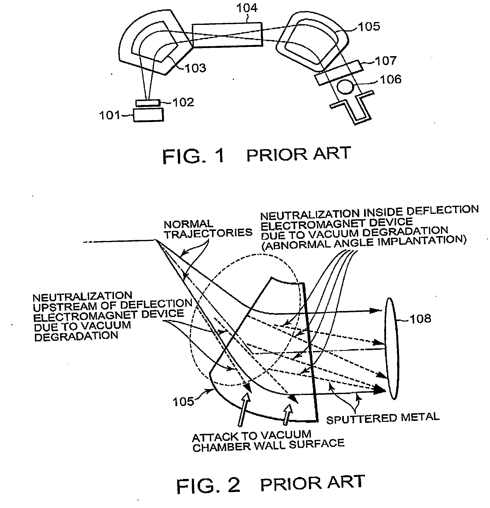
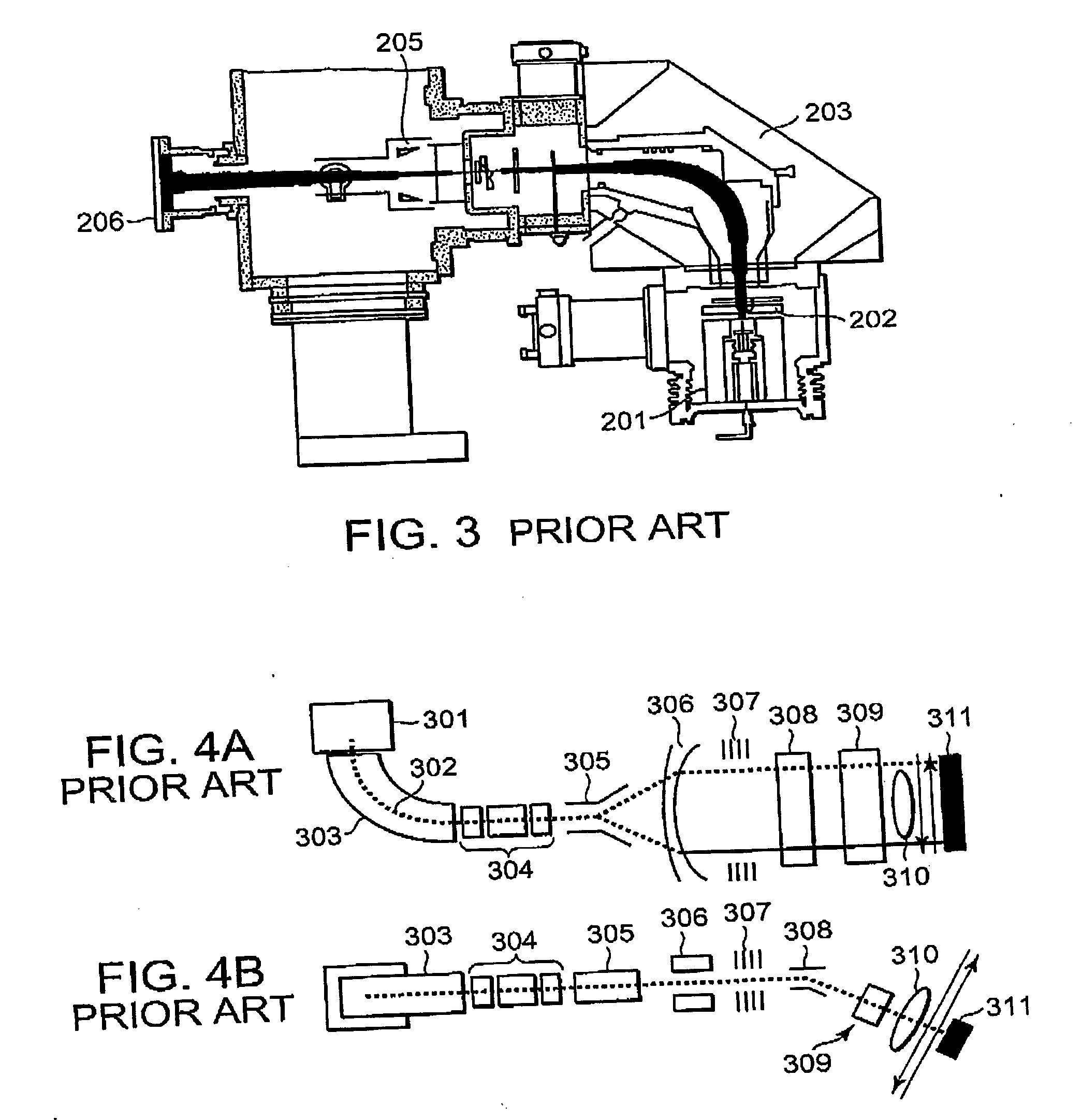
[0093] Prior to describing a preferred embodiment of this invention, description will be given hereinbelow about those points that are improved for applying this invention to an ion implantation system.

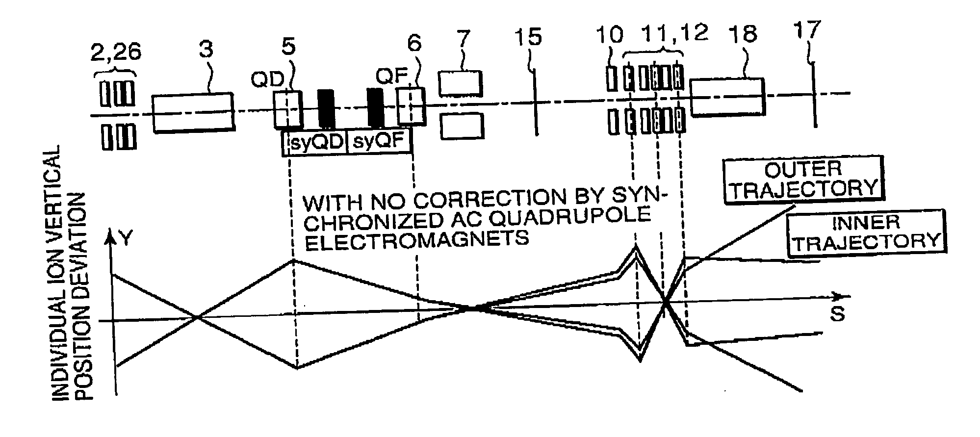
[0094] Note that a “horizontal axis” which will hereinafter be referred to represents one axis in a plane in a direction perpendicular to a beam advancing direction and in a plane formed by trajectories in the mass analysis dipole magnet (dispersive plane). Likewise, a “vertical axis” represents one axis in the plane in the direction perpendicular to the beam advancing direction and perpendicular to the horizontal axis. A “longitunal direction”represents the beam advancing direction. Thus the “horizontal” and “vertical” do not necessarily refer to the surface of the earth.

[0095] By this invention, a high-current beam has become able to be transported while keeping the ability of the beam scan type single-wafer middle-current ion implantation system that enables the ion implantation ...


PUM


Abstract

A method to increase low-energy beam current according to this invention is applied to an irradiation system with ion beam comprising a beam generation source, a mass analysis device, a beam transformer, a deflector for scanning, a beam parallelizing device, an acceleration/deceleration device, and an energy filtering device. The beam transformer comprises a vertically focusing DC quadrupole electromagnet QD and a longitudinally focusing DC quadrupole electromagnet QF. The beam transformer transforms a beam having a circular cross-section or an elliptical or oval cross-section to the beam has an elliptical or oval cross-section that is long in the scan direction in all the region of a beam line after deflection for scanning.

Description

[0001] This application claims priority to prior Japanese patent application JP 2004-347511, the disclosure of which is incorporated herein by reference. BACKGROUND OF THE INVENTION [0002] This invention relates to an improvement in an irradiation system with an ion beam, such as an ion implantation system. In the ion implantation system, an irradiation target is a wafer made of silicon on GaAs. [0003] Following shrinkage of semiconductor devices, great importance has been placed on ion implantation accuracy even in a high-current ion implantation process. Conventionally, it has been sufficient that variation in the number (dose) of implanted ions is 1% or less in the surface of a target wafer and among targets wafer to wafer. However, in the most advanced process, it is required to control, in addition to the dose accuracy, ion implantation angle accuracy and energy accuracy at low energy. Factors that reduce the implantation angle accuracy are classified as follows. [0004] (1) A c...

Claims


Application Information

Patent Timeline
Patent Type & Authority Applications(United States)
IPC IPC(8): B01D59/44
CPCH01J27/024H01J37/023H01J37/05H01J37/1474H01J37/1478H01J37/15H01J37/3007H01J37/3171H01J2237/0213H01J2237/022H01J2237/0458H01J2237/047H01J2237/0492H01J2237/061H01J2237/0835H01J2237/1536H01J2237/24405H01J2237/24507H01J2237/30477H01J2237/31705H01L21/265
Inventor KABASAWA, MITSUAKITSUKIHARA, MITSUKUNI
Owner SENCORP
Why Eureka
Try Eureka