Method and system for performing in-situ cleaning of a deposition system

a deposition system and in-situ cleaning technology, applied in chemical vapor deposition coating, metal material coating process, coating, etc., can solve the problems of poor deposition rate, low rate of current deposition system, and inability to deposition metal films, etc., to achieve the effect of higher deposition ra

Inactive Publication Date: 2006-06-01
GLOBALFOUNDRIES INC +1
View PDF18 Cites 57 Cited by
  • Summary
  • Abstract
  • Description
  • Claims
  • Application Information

AI Technical Summary

Benefits of technology

[0010] The present invention further provides a method for depositing a refractory metal film on a substrate with periodic in-situ cleaning of the vapor delivery system and process chamber to allow for a higher deposition rate. To that end, the method comprises depositing the refractory metal film on a desired number of substrates using a deposition system configured to perform thermal chemical vapor deposition (TCVD) from a metal precursor; and cleaning the deposition system, in particular the vapor delivery system and process chamber, following deposition of the refractory metal film on the desired number of substrates by introducing a cleaning composition formed in an in-situ cleaning system to the vapor delivery system of the deposition system adjacent the metal precursor evaporation system and flowing the cleaning composition through the vapor delivery system and into the process chamber.

Problems solved by technology

Additionally, the use of metal-carbonyls, such as ruthenium carbonyl, can lead to poor deposition rates due to their low vapor pressure and the transport issues associated therewith.
Overall, the inventor has observed that current deposition systems suffer from such a low rate, making the deposition of such metal films impractical.

Method used


Image

  • Method and system for performing in-situ cleaning of a deposition system
  • Method and system for performing in-situ cleaning of a deposition system
  • Method and system for performing in-situ cleaning of a deposition system

Examples


Embodiment Construction

[0015] In the following description, in order to facilitate a thorough understanding of the invention and for purposes of explanation and not limitation, specific details are set forth, such as a particular geometry of the deposition system and descriptions of various components. However, it should be understood that the invention may be practiced in other embodiments that depart from these specific details.

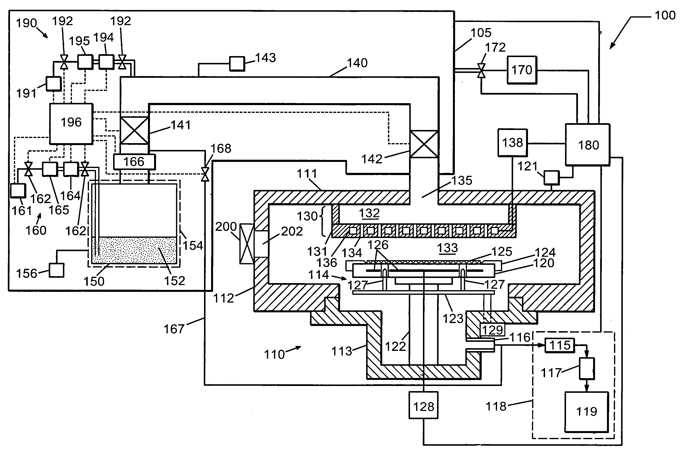
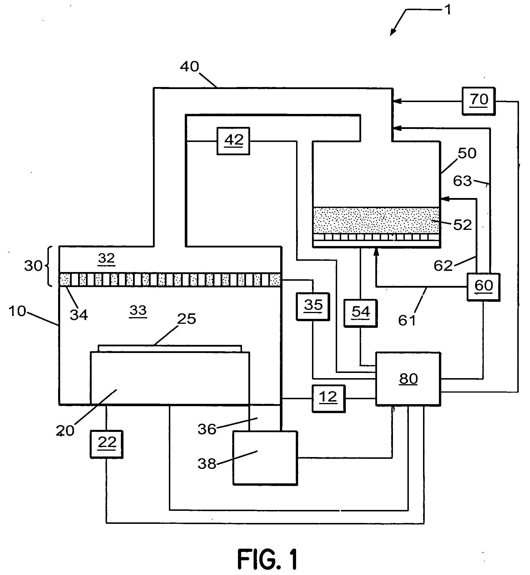
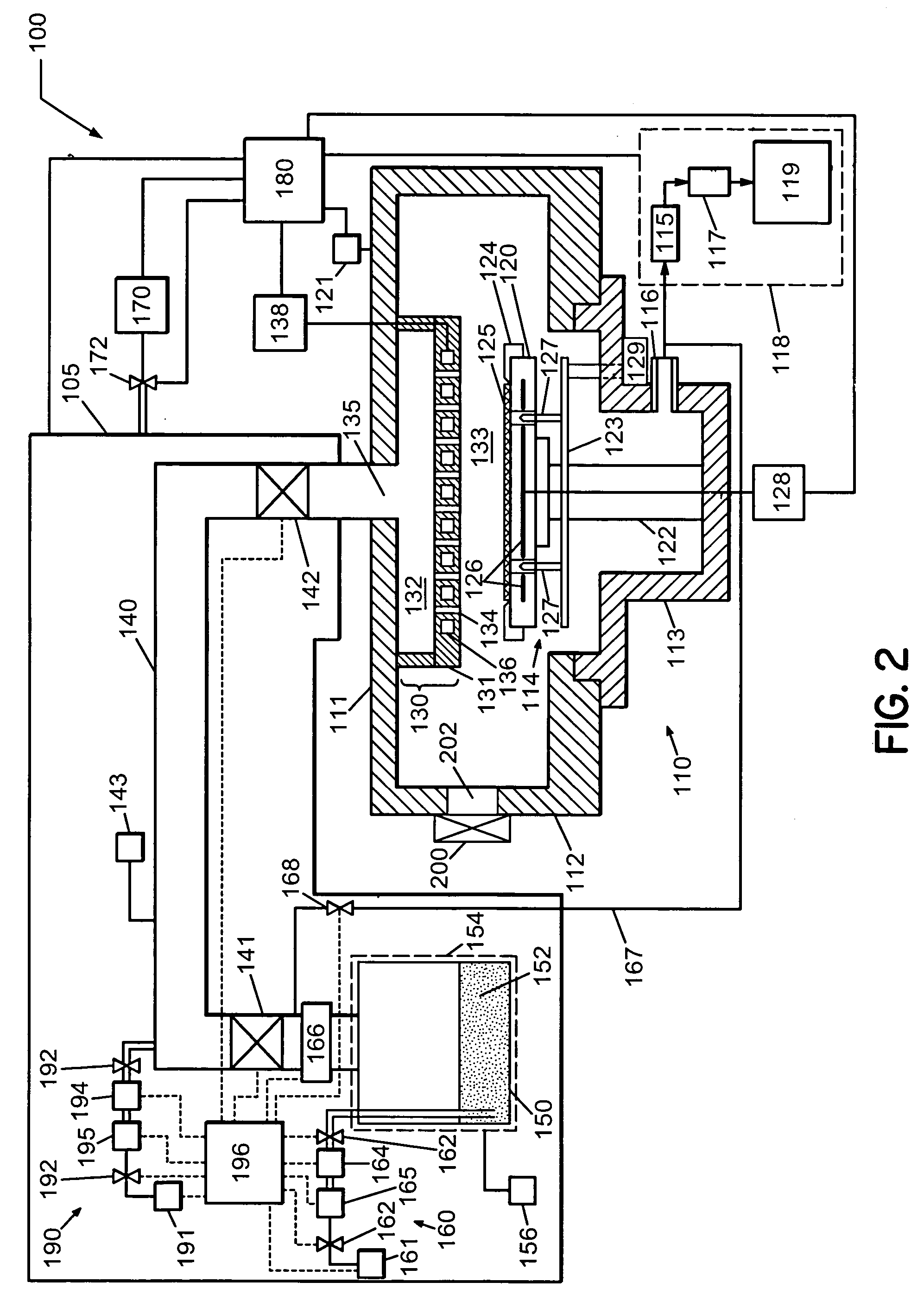
[0016] Referring now to the drawings, wherein like reference numerals designate identical or corresponding parts throughout the several views, FIG. 1 illustrates a deposition system 1 for depositing a metal film, such as a ruthenium (Ru) or a rhenium (Re) film, on a substrate according to one embodiment. The deposition system 1 comprises a process chamber 10 having a substrate holder 20 configured to support a substrate 25, upon which the metal film is formed. The process chamber 10 is coupled to a metal precursor evaporation system 50 via a vapor delivery system 40.

[0017] The ...


PUM

PropertyMeasurementUnit
temperatureaaaaaaaaaa

Abstract

A method for depositing metal layers, such as Ruthenium, on semiconductor substrates by a thermal chemical vapor deposition (TCVD) process includes introducing a metal carbonyl precursor in a deposition system, and depositing a metal layer from the metal carbonyl on a substrate. The TCVD process utilizes a short residence time for the gaseous species in the processing zone above the substrate to form a low-resistivity metal layer. In the deposition system, the metal carbonyl is evaporated in a solid precursor evaporation system, and the precursor vapor is transported to the process chamber via a vapor delivery system. Further, an in-situ cleaning system is coupled to the vapor delivery system in order to perform periodic cleaning of the deposition system. Periodic in-situ cleaning permits achieving a greater deposition rate by operating the deposition system at higher temperature where precursor vapor can decompose and potentially deposit on surfaces of the deposition system.

Description

BACKGROUND OF THE INVENTION [0001] 1. Field of the Invention [0002] The present invention relates to a method and system for thin film deposition, and more particularly to a method and system for high rate thin film deposition, wherein periodic in-situ cleaning is performed to remove precursor and deposition residue from both the process chamber and the vapor delivery system. [0003] 2. Description of Related Art [0004] The introduction of copper (Cu) metal into multilayer metallization schemes for manufacturing integrated circuits can necessitate the use of diffusion barriers / liners to promote adhesion and growth of the Cu layers and to prevent diffusion of Cu into the dielectric materials. Barriers / liners that are deposited onto dielectric materials can include refractive materials, such as tungsten (W), molybdenum (Mo), and tantalum (Ta), that are non-reactive and immiscible in Cu, and can offer low electrical resistivity. Current integration schemes that integrate Cu metallizatio...

Claims


Application Information

Patent Timeline
Patent Type & Authority Applications(United States)
IPC IPC(8): C23C16/00
CPCC23C16/16C23C16/4405C23C16/4481C23C16/4485
Inventor SUZUKI, KENJILEUSINK, GERRIT J.MCFEELY, FENTON R.MALHOTRA, SANDRA G.
Owner GLOBALFOUNDRIES INC
Why Eureka
Try Eureka