

Photoelectric converting apparatus
a technology of photoelectric conversion and conversion apparatus, which is applied in the direction of television system, television control device, television system scanning details, etc., can solve the problems of difficult construction of photoelectric conversion apparatus of a high sensitivity, significant decrease in output voltage, etc., and achieves low electric power consumption, simple configuration, and reduced noise
- Summary
- Abstract
- Description
- Claims
- Application Information
AI Technical Summary
Benefits of technology
Problems solved by technology
Method used
Image

Examples
first embodiment
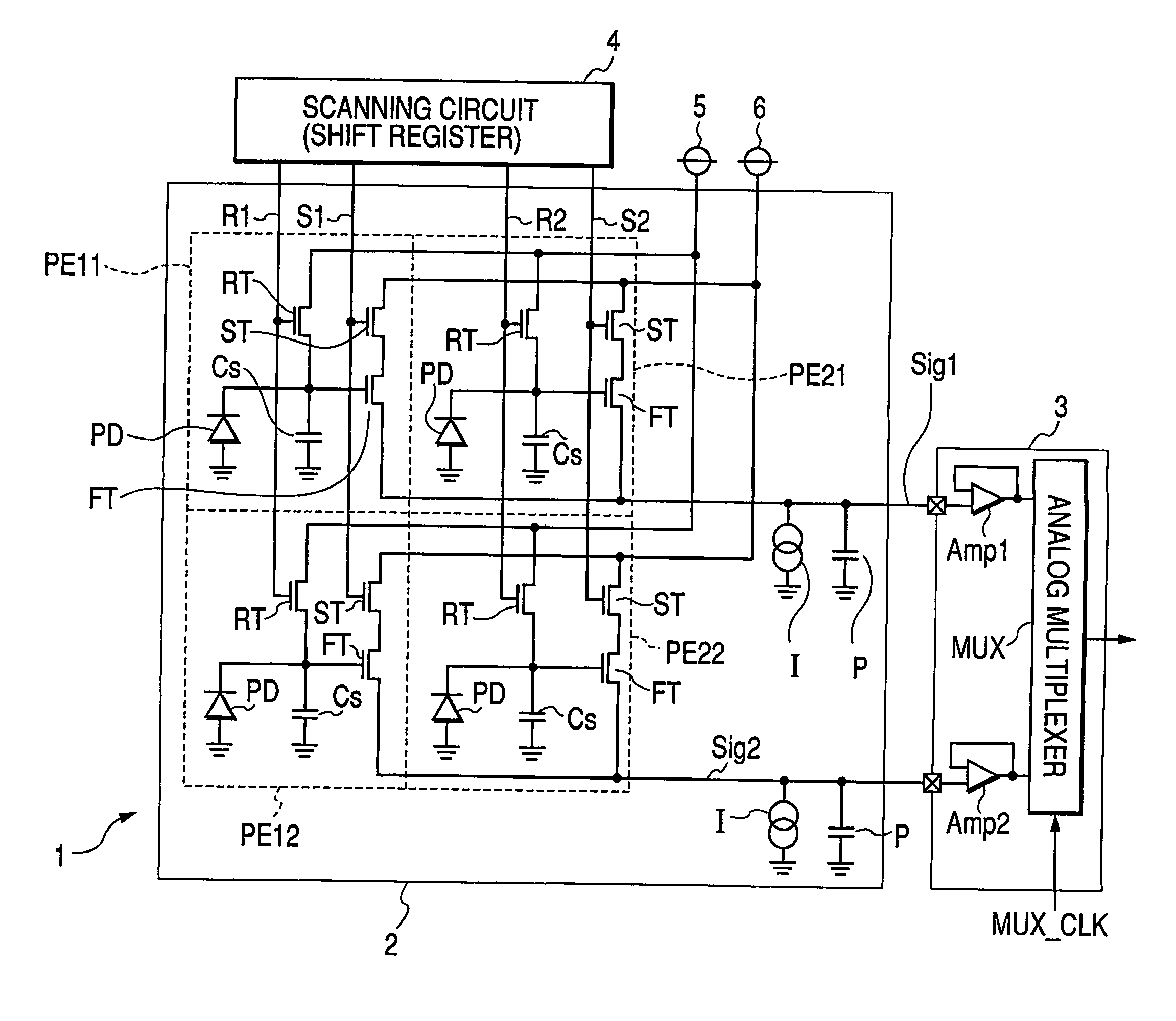
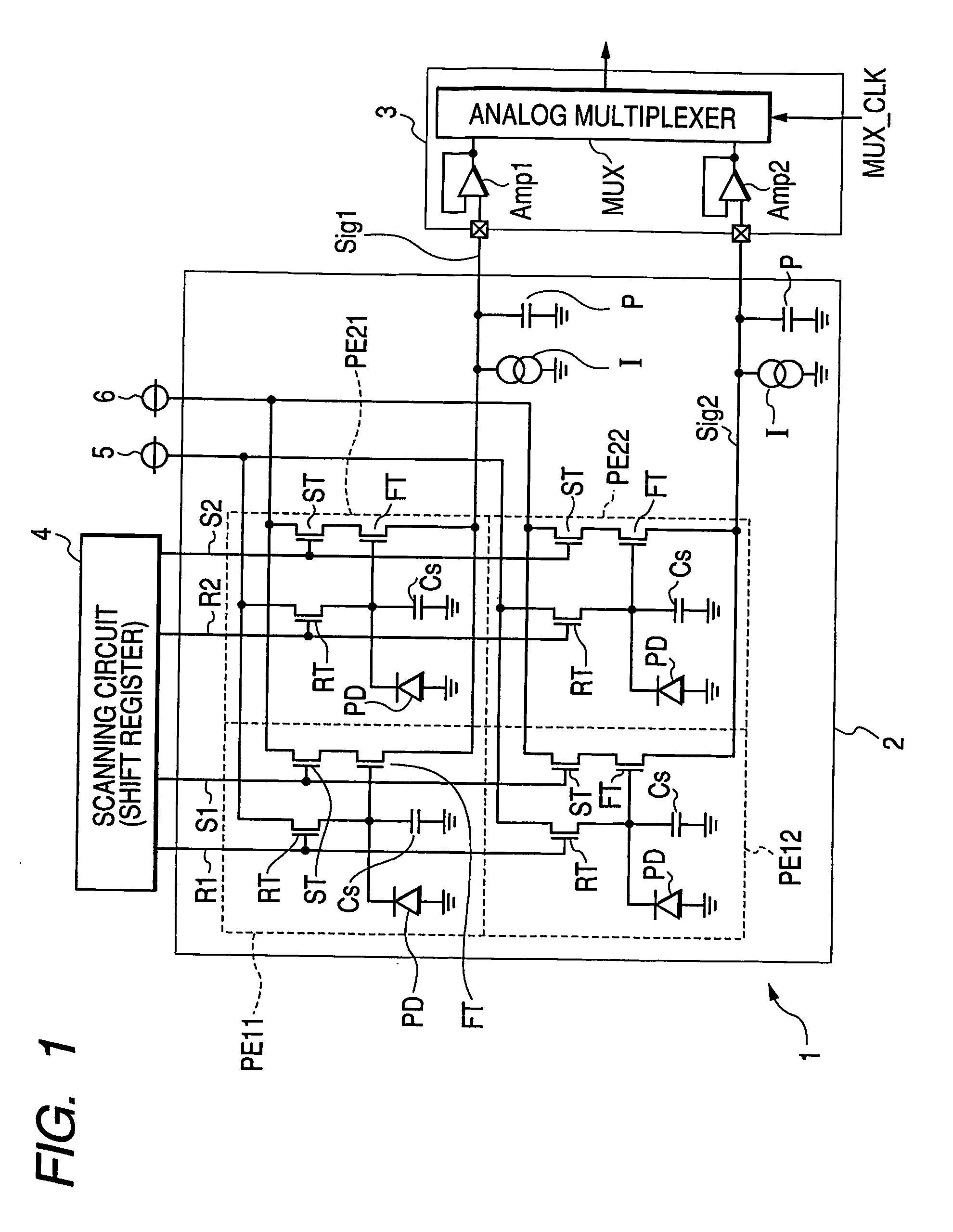
[0039] At first there will be explained a first embodiment of the present invention. FIG. 1 is a circuit diagram showing a circuit structure of a photoelectric converting apparatus, particularly an X-ray image pickup apparatus, constituting the first embodiment of the present invention.
[0040] In the present embodiment, a sensor array 1 is constructed on a glass substrate 2, by arranging four pixels PE11, PE12, PE21 and PE22 in two rows and two columns, but a number of pixels constituting the sensor array 1 is not limited to such example. Each pixel is provided with a photoelectric converting element PD constituted of a PIN photodiode formed with amorphous silicon, and a storage capacitance Cs for accumulating a signal charge generated by the photoelectric converting element PD. The photoelectric converting element PD and the storage capacitance Cs are grounded at one terminals thereof and are mutually connected at the other terminals. Each pixel is further provided with a resetting...
second embodiment
[0051] In the following, there will be explained a second embodiment of the present invention. FIG. 3 is a circuit diagram showing a circuit structure of a photoelectric converting apparatus, particularly an X-ray image pickup apparatus, constituting a second embodiment of the present invention. In the second embodiment, in place for the constant current source employed in the first embodiment, a thin film transistor (TFT) CT formed by amorphous silicon is provided. A gate of the thin film transistor CT receives a voltage from a power supply 7 for a constant current source. Such structure can be produced by a simple manufacturing process, as the constant current source can be simultaneously formed by film formations with other transistors (resetting, selecting and source follower). The thin film transistors for resetting, for selecting, for source follower and for constant current source may have same laminated film thicknesses or individually different film thicknesses. They may al...
third embodiment
[0056] In the following, there will be explained a third embodiment of the present invention. FIG. 5 is a circuit diagram showing a circuit structure of a photoelectric converting apparatus, particularly an X-ray image pickup apparatus, constituting a third embodiment of the present invention. In contrast to the second embodiment in which the thin film transistor CT constituting the constant current source is positioned between a pixel and the readout circuit 3, in the third embodiment, the thin film transistor CT is located, on the common signal line, at a position more spaced from the readout circuit 3 than the pixel. Stated differently, the pixel is positioned between the thin film transistor CT and the readout circuit 3.
[0057] An advantage of a spaced arrangement of the constant current source from the readout circuit will be explained with reference to FIGS. 15, 16 and 17. FIG. 15 shows a structure in which, for each signal line, the constant current source is spaced from the ...
PUM
 Abstract
Description
Claims
Application Information